Do you have a question about the ALTAI VX200 and is the answer not in the manual?
Lists all items included in the product box for setup.
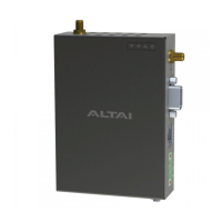
Illustrates the front, right, top, bottom, back, and left views of the device.
Explains the LED indicators and the first RP-SMA RF port.
Details the reset button, RS232 serial, and Ethernet (PoE) ports.
Describes the DC terminal block for power and the second RP-SMA RF port.
Covers screw holes for wall/DIN-rail mounting and chassis grounding.
Provides step-by-step instructions for mounting the unit on a 35mm DIN-rail.
Details the procedure for mounting the unit on a wall surface.
Instructions for connecting the device using a 12-48 VDC power source.
Guide for powering the device via an 802.3af/at-compliant PoE switch.
Steps to configure computer's IP settings for device access.
How to access the device's web-based management interface.
Steps to enable radio and set the device to Station mode.
Details on setting up WLAN security and viewing connection status.
Compliance statement regarding FCC rules for digital devices.
Statement regarding European conformity for radio interference.
Important warnings regarding installation and device handling.
Details manufacturer, distributor, and support contact information.
The Altai VX200 is a dual-band CPE/AP (Customer Premises Equipment/Access Point) designed for robust wireless connectivity. This device serves as a versatile solution for extending network coverage and providing reliable internet access in various environments. It can operate in multiple modes, including Station, Repeater, AP, and Bridge, offering flexibility for different deployment scenarios.
The primary function of the Altai VX200 is to establish and maintain wireless network connections. As a CPE, it acts as an endpoint device that connects to a larger wireless network, such as a remote access point, to provide internet access to local clients. In AP mode, it broadcasts a wireless signal, allowing other devices to connect to it and access the network. The dual-band capability means it can operate on both 2.4GHz and 5GHz frequencies, providing options for better performance and less interference depending on the environment.
The device supports various network configurations, making it suitable for a wide range of applications, from extending home networks to providing connectivity in industrial settings. It is equipped with an Ethernet port that supports PoE (Power over Ethernet), simplifying installation by allowing both power and data to be transmitted over a single cable. Additionally, it features a DC terminal block for direct power input, offering an alternative power option. A serial port (RS-232 DB9) is included for connecting peripheral serial devices, enabling remote access to these devices over the TCP/IP network via the VX200.
For robust wireless performance, the VX200 is designed to work with external 2.4G/5G antennae (purchased separately). It supports 2x2 MIMO (Multiple-Input Multiple-Output) WiFi connections, which enhances data throughput and signal reliability. The device also incorporates grounding features to protect against electrical surges, ensuring long-term stability and safety.
The Altai VX200 is designed for straightforward installation and configuration, though professional installation may be required depending on the deployment scenario. It offers multiple mounting options: DIN-rail mount and wall mount, providing flexibility for installation in different physical spaces. The quick setup guide provides clear instructions for attaching the device to a DIN rail or a wall, including details on drilling holes and securing the unit.
Powering the device can be achieved through two main methods: a 12-48 VDC direct current input via the terminal block or through an 802.3af/at-compliant PoE switch via the Ethernet port. This dual power option allows for adaptability to existing infrastructure. Once powered, the device's LED panel provides visual feedback on its operational status, including power, LAN (Ethernet) activity, and WiFi radio status (2.4G/5G). The LED indicators differentiate between off, flashing, and steady states to convey information such as no power, booting up, ready for service, disconnected, data transmitting/receiving, radio disabled, and various connection statuses in Station/Repeater, AP, and Bridge modes.
Configuration of the VX200 is performed through a web-based interface, accessible via a standard web browser. Users connect a computer to the device's Ethernet port and navigate to a default IP address. The interface is secured with default administrative credentials (username: admin, password: admin), which should be changed for security purposes after initial setup. The web interface allows users to configure the device's operating mode, wireless settings (such as SSID and security protocols), and other network parameters. For example, setting up the device in Station (CPE) mode involves enabling the radio, selecting "Station" as the radio mode, entering the remote SSID to connect to, and configuring the appropriate WLAN security settings (e.g., WPA2-Personal with a passphrase). The interface also provides a "Connection Info" section to monitor the status of the wireless connection, showing details like MAC address, SNR, RSSI, channel, data rate, and throughput.
The Altai VX200 includes several features to aid in maintenance and troubleshooting. A reset button on the device serves two critical functions:
The LED panel, as described in the usage features, is a key maintenance tool, providing immediate visual diagnostics of the device's operational state. This allows administrators to quickly identify if the device is powered, connected to the network, or actively transmitting data, helping to narrow down potential issues.
For physical maintenance, the device is designed with a metal chassis that may become hot during operation, and users are advised to exercise caution or use protection when handling it. The grounding point feature, requiring a 14 AWG ground wire connected to a reliable earth ground, is a crucial safety and maintenance aspect, protecting the device from electrical damage and ensuring stable operation.
The web-based interface not only facilitates initial configuration but also serves as a central point for ongoing monitoring and management. Users can check firmware versions, CPU load, and uptime, which are important for assessing device health and performance. The ability to view connection information, such as signal strength and data rates, helps in optimizing antenna alignment and troubleshooting connectivity issues. Regular firmware updates, while not explicitly detailed in the provided text, are typically managed through such an interface, ensuring the device benefits from the latest features, security patches, and performance improvements. The comprehensive setup guide itself acts as a maintenance resource, providing detailed instructions for re-installation or re-configuration if needed.
| Model | ALTAI VX200 |
|---|---|
| Category | Gateway |
| Product Type | Wireless Gateway |
| Wireless Standards | 802.11a/b/g/n/ac |
| Frequency Bands | 2.4 GHz, 5 GHz |
| Max Throughput | Up to 867 Mbps |
| Maximum Data Rate | 867 Mbps |
| Antenna Gain | 5 dBi |
| Ethernet Ports | 2 x 10/100/1000 Mbps |
| Power Supply | 48V DC |
| PoE | 802.3af/at |
| Dimensions | 260 x 260 x 70 mm |
| Weight | 1.5 kg |
| Channel Bandwidth | 20/40/80 MHz |
| Modulation | OFDM, DSSS |
| Transmit Power | Up to 26 dBm |
| Antenna | Omni-directional |
| Interface | Ethernet |
| Operating Temperature | -40°C to 60°C |
| Operating Mode | Access Point, Bridge |
| Frequency Range | 2.412 ~ 2.484 GHz, 5.150 ~ 5.850 GHz (subject to local regulations) |