DE1-SOC COMPUTER SYSTEM WITH NIOS II For Quartus II 15.0
4 Media Components
This section describes the audio in/out, video-out, video-in, PS/2, IrDA, and ADC ports.
4.1 Audio In/Out Port
The DE1-SoC Computer includes an audio port that is connected to the audio CODEC (COder/DECoder) chip on
the DE1-SoC board. The default setting for the sample rate provided by the audio CODEC is 48K samples/sec. The
audio port provides audio-input capability via the microphone jack on the DE1-SoC board, as well as audio output
functionality via the line-out jack. The audio port includes four FIFOs that are used to hold incoming and outgoing
data. Incoming data is stored in the left- and right-channel Read FIFOs, and outgoing data is held in the left- and
right-channel Write FIFOs. All FIFOs have a maximum depth of 128 32-bit words.
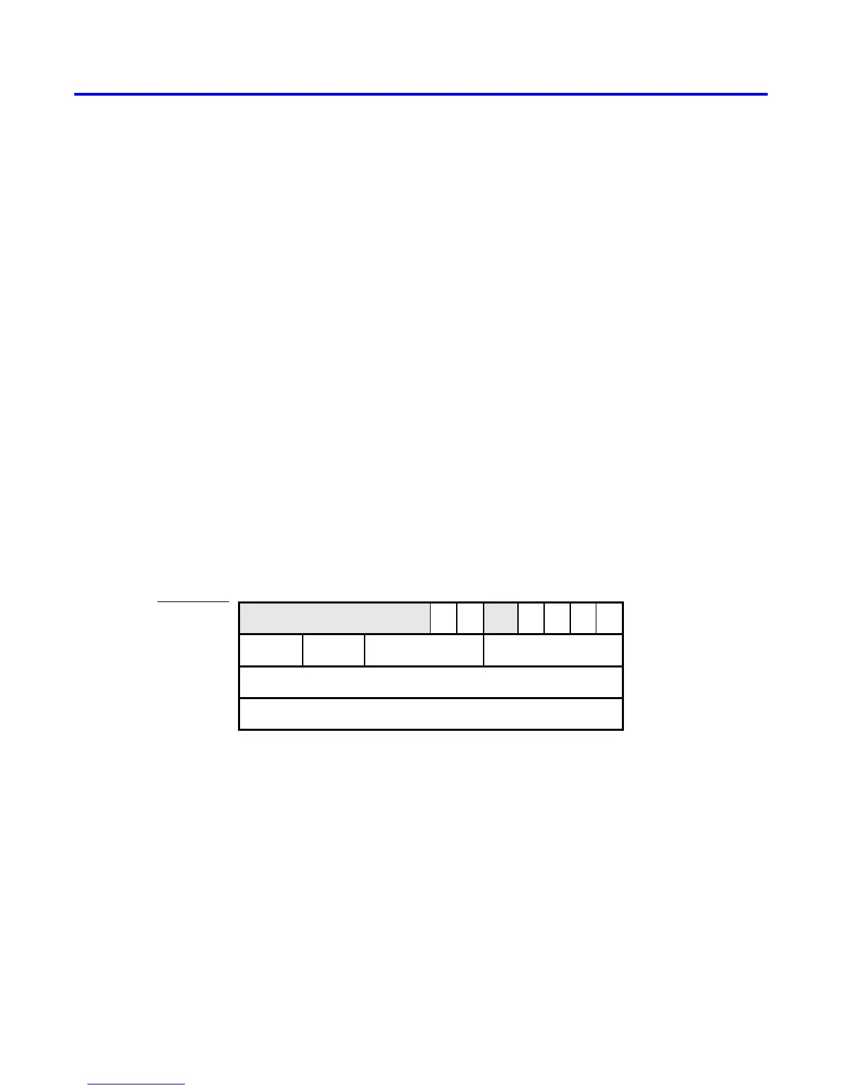
The audio port’s programming interface consists of four 32-bit registers, as illustrated in Figure 25. The Control
register, which has the address 0xFF203040, is readable to provide status information and writable to make control
settings. Bit RE of this register provides an interrupt enable capability for incoming data. Setting this bit to 1 allows
the audio core to generate a Nios II interrupt when either of the Read FIFOs are filled 75% or more. The bit RI will
then be set to 1 to indicate that the interrupt is pending. The interrupt can be cleared by removing data from the
Read FIFOs until both are less than 75% full. Bit WE gives an interrupt enable capability for outgoing data. Setting
this bit to 1 allows the audio core to generate an interrupt when either of the Write FIFOs are less that 25% full. The
bit WI will be set to 1 to indicate that the interrupt is pending, and it can be cleared by filling the Write FIFOs until
both are more than 25% full. The bits CR and CW in Figure 25 can be set to 1 to clear the Read and Write FIFOs,
respectively. The clear function remains active until the corresponding bit is set back to 0.
Address
01531
. . .
0xFF203040
0xFF203044
. . .
Unused WE RE
1
WSRC RALC RARCWSLC
16 223
Left data
0xFF203048
Right data
0xFF20303C
3
Control
CW CR
. . .
89
WI RI
710
. . .
24
Fifospace
Leftdata
Rightdata
Figure 25. Audio port registers.
The read-only Fifospace register in Figure 25 contains four 8-bit fields. The fields RARC and RALC give the number
of words currently stored in the right and left audio-input FIFOs, respectively. The fields WSRC and WSLC give the
number of words currently available (that is, unused) for storing data in the right and left audio-out FIFOs. When all
FIFOs in the audio port are cleared, the values provided in the Fifospace register are RARC = RALC = 0 and WSRC
= WSLC = 128.
The Leftdata and Rightdata registers are readable for audio in, and writable for audio out. When data is read from
these registers, it is provided from the head of the Read FIFOs, and when data is written into these registers it is
loaded into the Write FIFOs.
Altera Corporation - University Program
2015
31
 Loading...


