DE1-SOC COMPUTER SYSTEM WITH NIOS II For Quartus II 15.0
2.4.3 Slider Switch Parallel Port
The SW
9−0
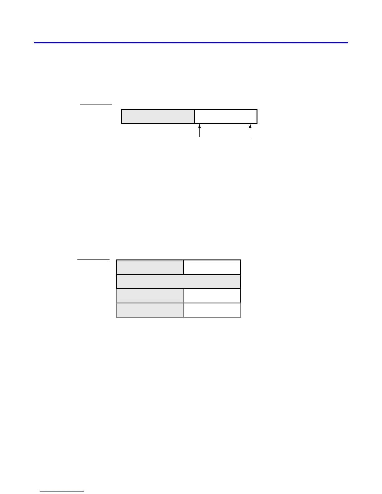
slider switches on the DE1-SoC board are connected to an input parallel port. As illustrated in Figure 5,
this port comprises a 10-bit read-only Data register, which is mapped to address 0xFF200040.
0xFF200040
SW
0
SW
9
Address
Data register
031 910
. . .Unused
Figure 5. Data register in the slider switch parallel port.
2.4.4 Pushbutton Key Parallel Port
The parallel port connected to the KEY
3−0
pushbutton switches on the DE1-SoC board comprises three 4-bit reg-
isters, as shown in Figure 6. These registers have the base address 0xFF200050 and can be accessed using word
operations. The read-only Data register provides the values of the switches KEY
3−0
. The other two registers shown
in Figure 6, at addresses 0xFF200058 and 0xFF20005C, are discussed in Section 3.
Address
0214331 30
. . .
0xFF200050
0xFF200058
0xFF20005C
Unused
KEY
3-0
Edge bits
Mask bits
Unused
Unused
Unused
Data register
Interruptmask register
Edgecapture register
Unused
Figure 6. Registers used in the pushbutton parallel port.
2.4.5 Expansion Parallel Port
The DE1-SoC Computer includes two bidirectional parallel ports that are connected to the JP1 and JP2 40-pin
headers on the DE1-SoC board. These parallel ports include the four 32-bit registers that were described previously
for Figure 2. The base address of the port for JP1 is 0xFF200060, and for JP2 is 0xFF200070. Figure 7 gives a
diagram of the 40-pin connectors on the DE1-SoC board, and shows how the respective parallel port Data register
bits, D
31−0
, are assigned to the pins on the connector. The figure shows that bit D
0
of the parallel port is assigned
to the pin at the top right corner of the connector, bit D
1
is assigned below this, and so on. Note that some of the
pins on the 40-pin header are not usable as input/output connections, and are therefore not used by the parallel ports.
Also, only 32 of the 36 data pins that appear on each connector can be used.
Altera Corporation - University Program
2015
5