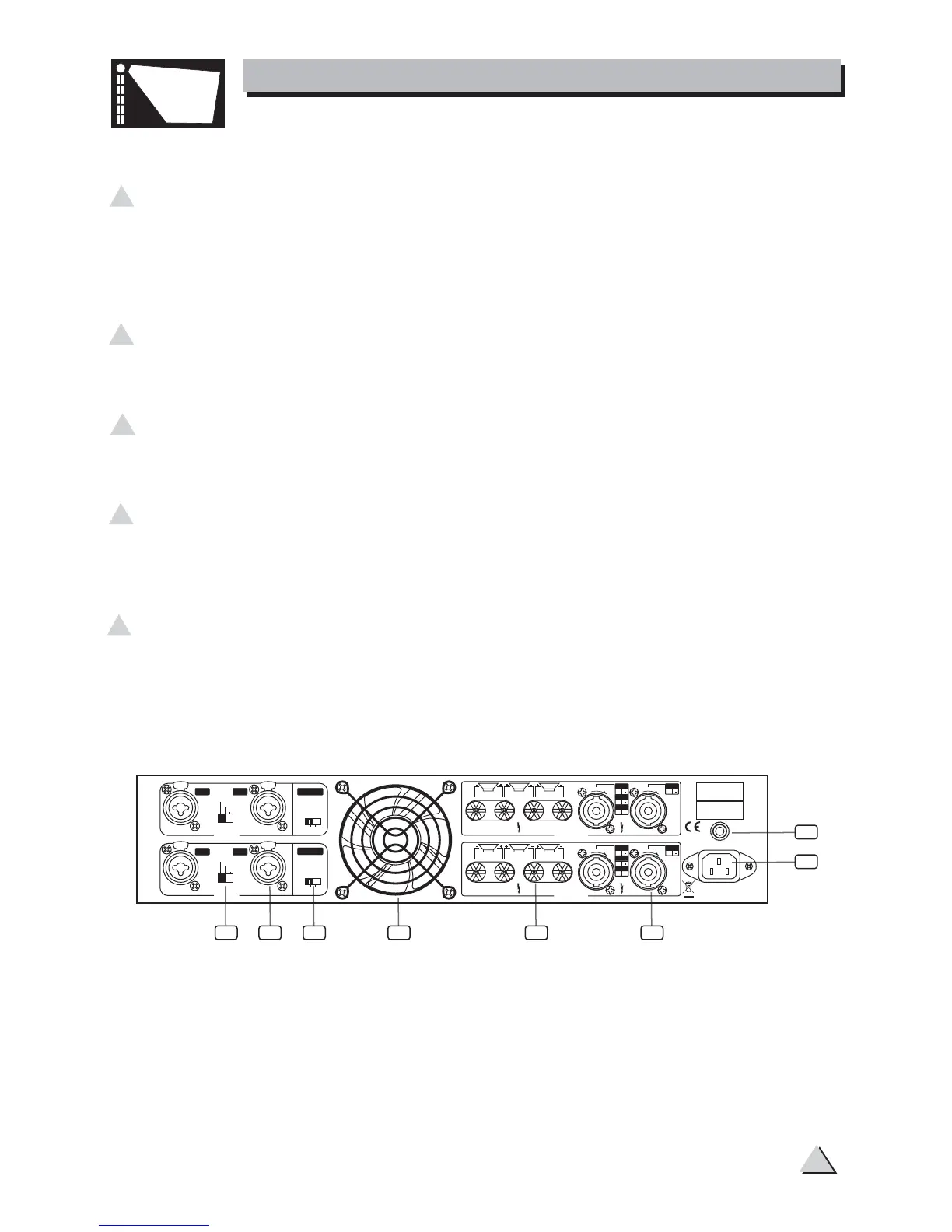
Rear Panel:
7 CIRCUIT BREAKER
This is an electronic fuse for protecting the unit from possible damage. When the
unit is overloaded or the temperature inside the unit is too high, this push-type
button will spring out and disconnect the power supply. Push the Breaker to restore
normal working conditions.
8 IEC socket for AC power cable
Connect the supplied main cord. Do not insert the power cord into the D amplifier
and into the AC Outlet until voltage has been correctly set.
9 COMBO BALANCED INPUT CONNECTORS
Each Channel features balanced combo connector that used to input the signal to
the amplifier.
10 SPEAKON OUTPUTS
These connectors are specifically designed to connect high power speakers. The
correct polarity is secured automatically, they prevent shock hazard and they lock-in
securely.
11 BINDING POST OUTPUTS
Please make sure to respect the speaker polarity when using binding post.
Turn off the unit before connecting an audio signal to the binding post to
avoid any electric shock!
Caution:
3. CONTROL ELEMENTS
SPOTLIGHT
6
7
8
9 10111213 14
OFF ON
LF 30HZ
FILTER
BRIDGED
CH1 CH2
CH3 CH4
OFF ON
LF 30HZ
FILTER
STEREO
PARALLEL
BRIDGED
BRIDGED
MONO
BRIDGED
MONO
OUTPUT
OUTPUT
CH3
CH1
CH4
CH2
CH1/CH2
CH3/CH4
CH1
1+
2+
1+
1
2
2+
BR DGED
CH2
L
O
K
L
O
K
CH3
1+
2+
1+
1
2
2+
BR DGED
CH4
L
O
K
L
O
K
BRIDGED
INPUT
STEREO
PARALLEL
B IDGED
CH2
1 1
CH4
1 1
INPUT
SERIA
MODE
BREAKER
MADE N CH NA
220 240V 50/60Hz
Rated Power
Consumpt on 3000W
DESIGNED N I ALY
PUSHPUSH
PUSHPUSH