7
- function selector
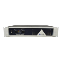
Clip limit : set these small dip switches of 1(ON) and 10(ON) at "ON" position , then the clip limit of channel 1
and channel 2 has been working; once the output level is reach or exceed the level that is predetermined by the
threshold setting selected. It may result in the undesirable distortion .In order to avoid the distortion, the clip begins;
if the dip switch are set at "OFF", the clip limit doesn't work.
CLIP LIMIT
ON
OFF
ON
OFF
23456789
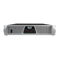
Filter: this unit are equipped with two low cut filter eliminating unwanted low- frequency signals like rumble noise:
75Hz and 35Hz. You will activate 35Hz low cut filter by Turning these two small dip switches of 2 and 9 up to the
top, and turn these two small dip switches down, you will choose 75Hz low cut filter.
12
14
13
35Hz FILTER
FILTER OFF
FILTER OFF
35Hz FILTER
FILTER ON
75Hz FILTER
75Hz FILTER
FILTER ON
1
4
5
67 10
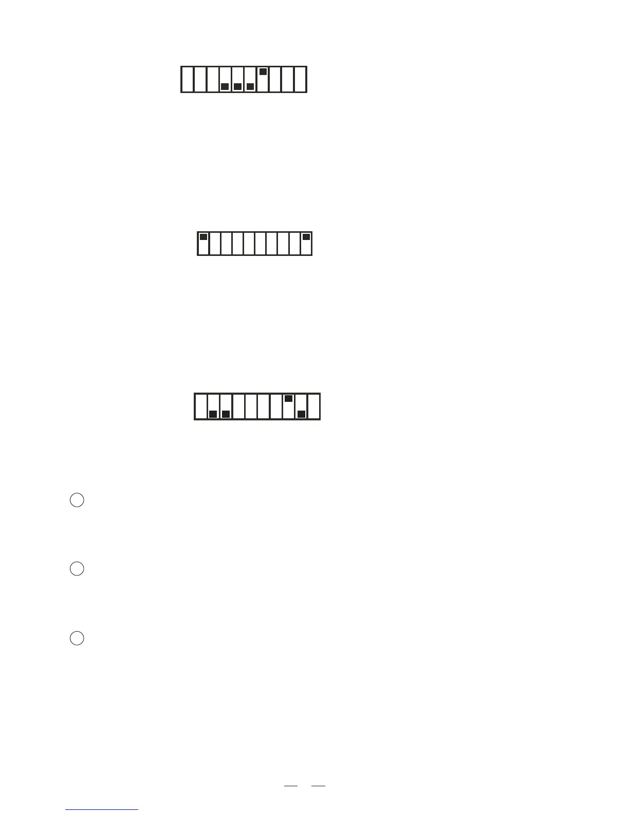
Please refer to chapter 5 for the connection of loads in detain.
BRIDGE MODE
12
3
4
56
7
8910
Output Terminal
You can output the powered signal by the specific output connectors according to the actual application
circumstance. Caution: turn off the unit before connecting the output connectors so as to avoid any electric
shock!
Breaker
This switch works as fuse for protecting the unit from damage. When the unit is overloaded or the temperature
inside the unit is too high, this push-button will spring up and break the power supply. The power supply will be
restored with pushing this switch again.
Power cord
It connects to the main power. Please check the voltage accepted by the unit and the voltage available from
your AC sockets before connecting the unit to the mains.
 Loading...