ACMS8/CB Sub-Assembly - 3 -
Installation Instructions:
Wiring methods shall be in accordance with the National Electrical Code NFPA 70/NFPA 72/ ANSI / Canadian
Electrical Code / CAN/ULC-S524/ULC-S527/ULC-S537, and with all local codes and authorities having
jurisdiction. Product is intended for indoor dry use only.
1. Refer to Sub-Assembly Installation Instruction for mounting Rev. MS050913.
Carefully review:
Terminal Identification Table (pg. 4) Typical Application Diagram (pg. 7)
LED Diagnostics (pg. 4) Hook-up Diagrams (pg. 8-9)
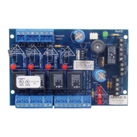
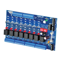
2. Ensure all output jumpers [OUT1] - [OUT8] are placed in the OFF (center) position.
3. Connect low voltage DC power supplies to terminals marked [+ PWR1 –], [+ PWR2 –]
4. Set each output [OUT1] - [OUT8] to route power from power supply 1 or 2
(Fig. 1, pg. 3).
Note: Measure output voltage before connecting devices.
This helps avoiding potential damage.
5. Turn power off before connecting devices.
6. Output options: The ACMS8(CB) will provide up to eight (8) switched power
outputs or eight (8) dry form “C” outputs, or any combination of both switched
power and form “C” outputs, plus eight (8) unswitched auxiliary power outputs.
Switched Power outputs:
Connect the negative (–) input of the device being powered to the terminal marked [COM].
• For Fail-Safe operation connect the positive (+) input of the device being powered to the terminal
marked [NC].
• For Fail-Secure operation connect the positive (+) input of the device being powered to the terminal
marked [NO].
Form “C” outputs:
When form “C” outputs are desired, the corresponding jumper (1-8) must be placed in the OFF position
(Fig. 1, pg. 3). Alternatively, the corresponding output fuse (1-8) can be removed (ACMS8 only).
Connect negative (–) of the power supply directly to the locking device.
Connect the positive (+) of the power supply to the terminal marked [C].
• For Fail-Safe operation connect the positive (+) of the device being powered to the terminal
marked [NC].
• For Fail-Secure operation connect the positive (+) of the device being powered to the terminal
marked [NO].
Dry contacts rated @ 3A.
Auxiliary Power outputs (unswitched):
Connect positive (+) input of the device being powered to the terminal marked [C] and the negative (–)
of the device being powered to the terminal marked [COM]. Output can be used to provide power for
card readers, keypads etc.
7. Turn main power on after all devices are connected
8. Input Trigger options:
Note: If Fire Alarm disconnect is not used, connect a 10K ohm resistor to terminals marked [GND and EOL],
plus connect a jumper to terminals marked [GND, RST].
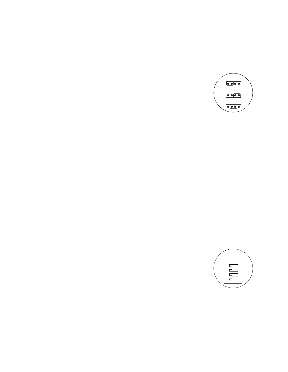
Normally Open (NO) Input:
Slide input control logic DIP switch into the ON position for [Switch 1-8]
(Fig. 2, on right). Connect your wires to terminals marked
[+ INP1 –] to [+ INP8 –].
Normally Closed (NC) Input:
Slide input control logic DIP switch into the OFF position for [Switch 1-8]
(Fig. 2, on right). Connect your wires to terminals marked
[+ INP1 –] to [+ INP8 –].
Open Collector Sink Input:
Connect the open collector sink input to the terminal marked
[+ INP1 –] to [+ INP8 –].
Wet (Voltage) Input Configuration:
Carefully observing polarity, connect the voltage input trigger wires and the supplied 10K resistor to
terminals marked [+ INP1 –] to [+ INP8 –].
If applying voltage to trigger input - set the corresponding INP Logic switch to the “OFF” position
If removing voltage to trigger input - set the corresponding INP Logic switch to the “ON” position.
 Loading...