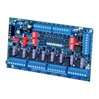
ACMS8/CB Sub-Assembly - 9 -
Fig. 10 - Polarity reversal input from FACP
signaling circuit output (polarity is
referenced in alarm conditiion).
Non-Latching.
FACP
FACP
+ --
Jumper
EOL
NC RST EOL +F +R
C GND GND -F -R
Fig. 11 - Polarity reversal input from FACP
signaling circuit output (polarity is
referenced in alarm condition).
Latching.
FACP
FACP
+ --
N.O.
Switch
EOL
NC RST EOL +F +R
C GND GND -F -R
Hook-Up Diagrams:
FACP
FACP
Jumper
10K
EOL
NC RST EOL +F +R
C GND GND -F -R
Fig. 12 - Normally Closed trigger input
(Non-Latching).
FACP
FACP
Jumper
10K
EOL
NC RST EOL +F +R
C GND GND -F -R
Fig. 13 - Normally Closed trigger input
(Latching).
FACP
FACP
NC RST EOL +F +R
C GND GND -F -R
N.O.
Switch
Jumper
EOL
Fig. 14 - Normally Open trigger input
(Non-Latching).
FACP
FACP
NC RST EOL +F +R
C GND GND -F -R
N.O.
Switch
EOL
N.O.
Switch
Fig. 15 - Normally Open trigger input
(Latching).

 Loading...