-
4
- ACMCBseries
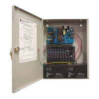
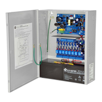
4. Connect AC (Fig. 2, pg. 6):
C
onnect unswitched AC power (115VAC 60Hz) to terminals marked [L, G, N]. Use 14 AWG or larger for all power
c
onnections. Secure green wire lead to earth ground.
K
eep power limited wiring separate from non-power limited
w
iring (115VAC 60Hz Input, Battery Wires). Minimum .25” spacing must be provided.
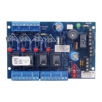
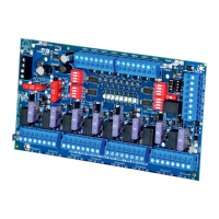
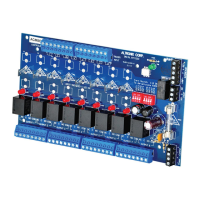
5. Output options (Fig. 1, pg. 5):
The unit will provide eight (8) switched power outputs or eight (8) unswitched auxiliary power outputs.
(a) Switched Power outputs:
Connect the negative (-) input of the device being powered to the terminal marked [COM]. For Fail-Safe operation
connect the positive (+) input of the device being powered to the terminal marked [NC]. For Fail-Secure operation
connect the positive (+) input of the device being powered to the terminal marked [NO].
(b) Auxiliary Power outputs (unswitched):
Connect positive (+) input of the device being powered to the terminal marked [C] and the negative (-) of the device
being powered to the terminal marked [COM]. Output can be used to provide power for card readers, keypads etc.
6.
Input trigger options (Fig. 1, pg. 5):
(a) Normally Open [NO] input trigger:
Inputs 1-8 are activated by normally open or open collector sink inputs.
Connect devices (card readers, keypads, request to exit buttons etc.) to terminals marked [IN] and [GND].
(b) Open Collector Sink inputs:
Connect the access control panel open collector sink positive (+) to the terminal marked [IN] and the negative (-) to
the terminal marked [GND].
7.
Fire Alarm Interface options (Figs. 4 through 8, pg. 8):
A normally closed [NC], normally open [NO] input or polarity reversal input from FACP signaling circuit will
trigger selected outputs. To enable FACP Disconnect for an output open the corresponding switch [SW1-SW8].
To disab
le FACP disconnect for an output close the corresponding switch [SW1-SW8].
(a) Normally Open [NO] input:
For non-latching hook-up (Fig. 5, pg. 8). For latching hook-up (Fig. 6, pg. 8).
(b) Normally Closed [NC] input:
For non-latching hook-up (F
ig. 7, pg. 8)
. F
or latching hook-up
(F
ig. 8, pg. 8)
.
(c) FACP Signaling Circuit input trigger:
Connect the positive (+) and negative (-) from the FACP signaling circuit output to the terminals marked [+ INP -].
Connect the FACP EOL to the terminals marked [+ RET -] (polarity is referenced in an alarm condition).
Jumper J3 must be cut
(Fig. 4, pg. 8).
8.
FACP Dry form “C” output (Fig. 1A, pg. 5):
Connect desired device to be triggered b
y the unit’
s dry contact output to the ter
minals marked [NO] and [C]
FACP for normally open output or the terminals marked [NC] and [C] FACP for normally closed output.
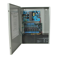
9. Battery Connections
(F
ig. 2, pg. 6)
:
For Access Control applications batteries are optional. If batteries are not used a loss of AC will result in the loss of
output voltage. Batteries must be lead acid or gel type. Connect one (1) 12VDC battery to the terminals marked
[- B
AT +] for 12VDC operation. Use two (2) 12VDC batteries wired in series for 24VDC operation.
10.
Battery and AC Supervision output (Fig. 2, pg. 6):
It is required to connect supervisory trouble reporting devices to outputs marked [AC Fail, BAT FAIL] supervisory
relay outputs marked [NC, C, NO] to appropriate notification devices. Use 22 AWG to 18 AWG for AC Fail &
Low/No Battery reporting. Cut “AC delay” jumper to delay report 6 hour.
Note: A tamper s
witch must be installed and connected to the appropriate notification device to report a
troub
le condition w
hen the enclosure door is open.
11.
Multiple power supply inputs (Fig. 1, pg. 5):
When using two (2) power supplies jumpers J1 and J2 (located to the left of the power/control terminals) must
be cut
(Fig. 1B, pg. 5 & Fig. 3 pg. 8). Connect power for the ACM8CB to the terminals marked [- Control +] and
connect power for the locking devices to the terminals marked [- Power +]. When using DC power supplies polarity
must be observed. When using AC power supplies polarity need not be observed.
Note: For UL compliance the additional power supply must be power limited, UL Listed for Access Control
Systems and accessories.
Maintenance:
Unit should be tested at least once a year for the proper operation as follows:
Output Voltage Test: Under normal load conditions, the DC output voltage should be checked for proper voltage level
 Loading...