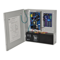
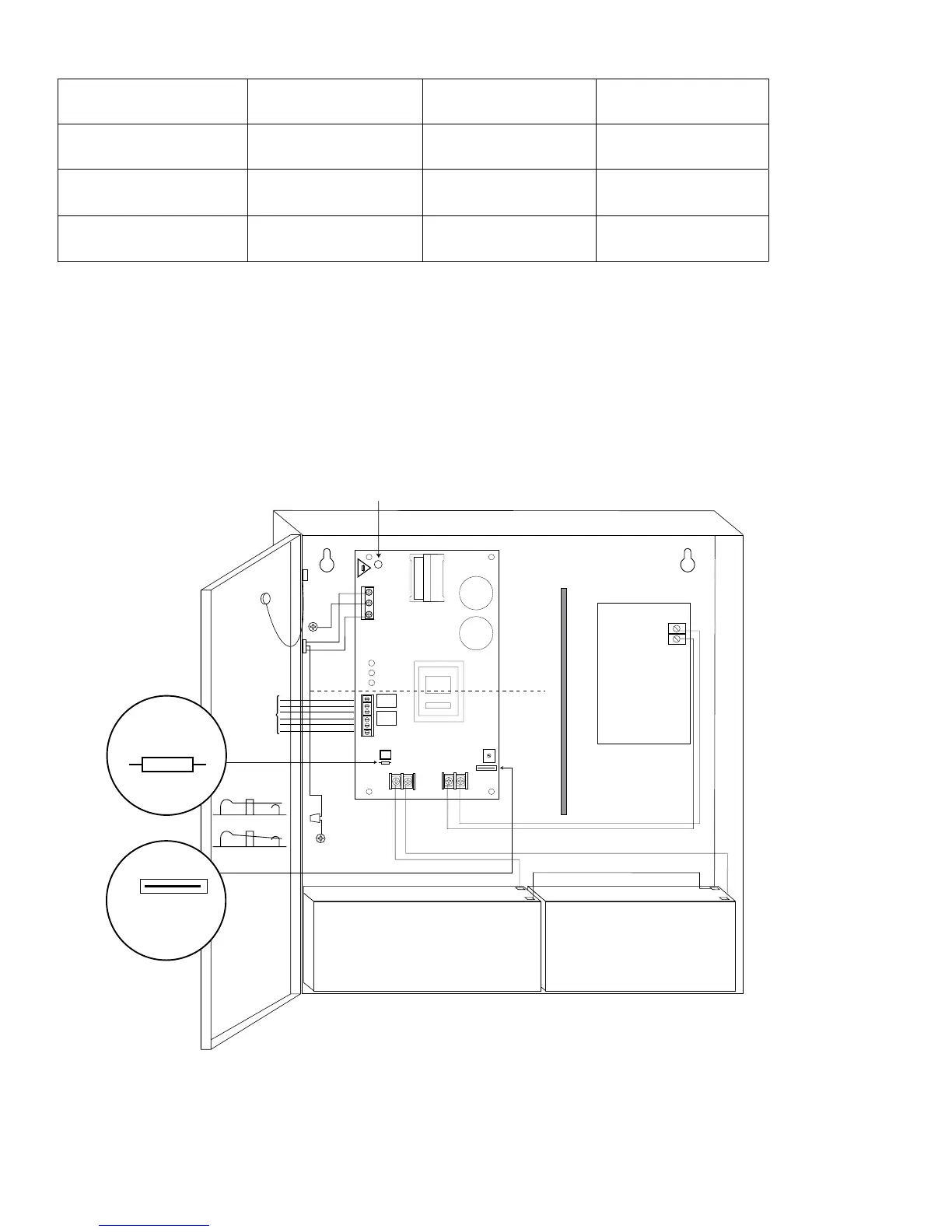
Door
CAUTION: De-energize unit prior to servicing. For continued protection against
risk of electric shock and fire hazard replace fuse with the same type and rating
5A, 250V. Do not expose to rain or moisture.
Green
Lead
Battery connection (non powe r-limited)
Wire
Strap
(from
Enclosure
to Door)
115VA C
power mains
non powe r-
limited
Battery & AC
Supervision
Circuit
(power limited)
Class 1
Power
Distribution
Module(s)
INPUT
Divider
non power-limited
Green
Lead
* 12VDC operation: For 12VDC operation only a single battery is needed. Connect red battery lead to terminal marke
[+ BAT] and to the [positive (+)] terminal of the battery . Connect black battery lead to terminal marked [BA T -] and
to the [negative (-)] terminal of the battery .
24VDC operation: Connect two (2) 12VDC batteries in series.
Keep power limited wiring separate from non-power limited. Use minimum .25" spacing.
Optional 12VDC Battery* Optional 12VDC Battery*
+ DC - - -
BAT FAIL
NC C NO NC C NO
+ BAT - - -
AC FAIL
DCAC BAT
L G N
5A 250V
OPEN - 24V
CLOSED - 12V
AC Delay
OPEN - 24V
CLOSED - 12V
AL600ULX Series - 3 -
Stand-by Specifications (total current shown):
Output 4 hr. of Stand-by &
5 Minutes of Alarm
24 hr. of Stand-by &
5 Minutes of Alarm
60 hr. of Stand-by &
5 Minutes of Alarm
12VDC / 40AH Battery Stand-by = 6.0 amp
Alarm = 6.0 amp
Stand-by = 1.0 amp
Alarm = 6.0 amp
Stand-by = 300mA
Alarm = 6.0 amp
24VDC / 12AH Battery -------- Stand-by = 200mA
Alarm = 6.0 amp
--------
24VDC / 40AH Battery Stand-by = 6.0 amp
Alarm = 6.0 amp
Stand-by = 1.0 amp
Alarm = 6.0 amp
Stand-by = 300mA
Alarm = 6.0 amp
Installation Instructions:
WiringmethodsshallbeinaccordancewiththeNationalElectricalCode/NFPA70/NFPA72/ANSI,andwithalllocal
codes and authorities having jurisdiction. Product is intended for indoor use only.
1. Mount unit in desired location, (Wiring, pg. 6). Mark and predrill holes in the wall to line up with the top two
keyholesintheenclosure.Installtwoupperfastenersandscrewsinthewallwiththescrewheadsprotruding.Place
the enclosure’s upper keyholes over the two upper screws, level and secure. Mark the position of the lower two holes.
Remove the enclosure. Drill the lower holes and install the two fasteners. Place the enclosure’s upper keyholes over the
twoupperscrews.Installthetwolowerscrewsandmakesuretotightenallscrews(Enclosure Dimensions, pg. 6-7).
Fig. 1
O PEN SWITCH
CLOSED SWITCH
Fig. 1a
Fig. 1b