- 10 - M series
Terminal Identification Tables:
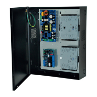
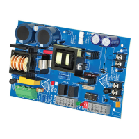
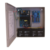
Power Supply Board
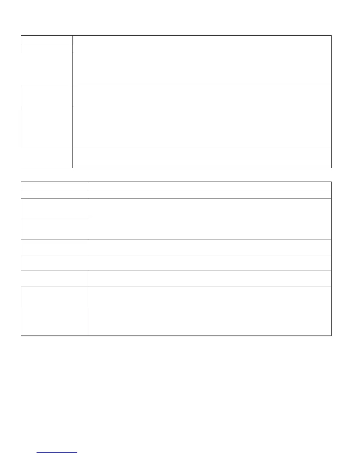
Terminal Legend Function/Description
L, G, N Connect 115VAC 60Hz to these terminals: L to hot, N to neutral.
+ DC –
AL300ULM - 12VDC/24VDC @ 2.5A to MOM5 board (power-limited).
AL400ULM - 12VDC @ 4A or 24VDC @ 3A to MOM5 board (power-limited).
AL600ULM - 12VDC/24VDC @ 6A to MOM5 board (power-limited).
AL1012ULM - 12VDC @ 10A to MOM5 board (power-limited).
AL1024ULM - 24VDC @ 10A to MOM5 board (power-limited).
AC FAIL
NC, C, NO
Indicates loss of AC power, e.g. connect to audible device or alarm panel. Relay normally energized when
AC power is present. Contact rating 1A @ 28VDC. AC or brownout fail is reported within 1 minute of event.
To delay reporting for up to 6 hrs., cut “AC delay” jumper and reset power to the unit.
BAT FAIL
NC, C, NO
Indicates low battery condition, e.g. connect to alarm panel. Relay normally energized when DC power is
present. Contact rating 1A @ 28VDC. A removed battery is reported within 5 minutes. Battery reconnection
is reported within 1 minute.
Low battery threshold:
12VDC output threshold set @ approximately 10.5VDC.
24VDC output threshold set @ approximately 21VDC.
+ BAT –
Stand-by battery connections.
AL300ULXB2, AL400ULXB2, AL600ULXB and AL1012ULXB (Power Supply Board)
maximum charge current is 0.7A. AL1024ULXB2 maximum charge current is 3.6A.
MOM5 - Output Module
Terminal Legend Function/Description
--- DC INPUT + 12VDC or 24VDC from power supply.
TRIGGER
Dry normally open [NO] or normally closed [NC] supervised (2.2K EOL resistor) input trigger. A short
or open circuit will transfer power from terminals marked [POS. (+) DC OUTPUT (STAND-BY)] to
terminals marked [POS (+) DC OUTPUT (ALARM)].
--- INPUT +
Wet (5-30VDC) input trigger. Applying voltage to these terminals in the polarity shown will
transfer power from terminals marked [POS. (+) DC OUTPUT (STAND-BY)] to terminals marked
[POS. (+) DC OUTPUT (ALARM)] (e.g. fire alarm control panel indications circuit).
NEG. 1
THROUGH NEG. 5
Supplies constant negative (-) voltage.
POS. (+) DC OUTPUT
(ALARM) 1-5
Supplies positive (+) voltage when dry trigger input or fire alarm wet trigger input is applied.
POS. (+) DC OUTPUT
(STAND-BY) 6-10
Supplies positive (+) voltage in normal condition. Power is removed when dry trigger input
or fire alarm wet trigger input is applied.
NC, C, NO
DRY OUTPUT
When the MOM5 is triggered the terminals marked [C and NO] will open and the terminals marked [C
and NC] will close. This output is used to trigger auxiliary devices. (e.g. HVAC Shutdown, Elevator
Recall etc.) Contact rating 1A @ 28VDC.
NC, C, NO
POWER FAIL
Form “C” contacts used for reporting no voltage is present at [-- DC INPUT +] terminals.
Under normal conditions, terminals marked [NO and C] are open, [NC and C] are closed.
A loss of power causes terminals marked [NO and C] to close and [NC and C] to open.
Contact rating 1A @ 28VDC.
 Loading...