M Series - 7 -
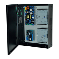
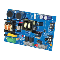
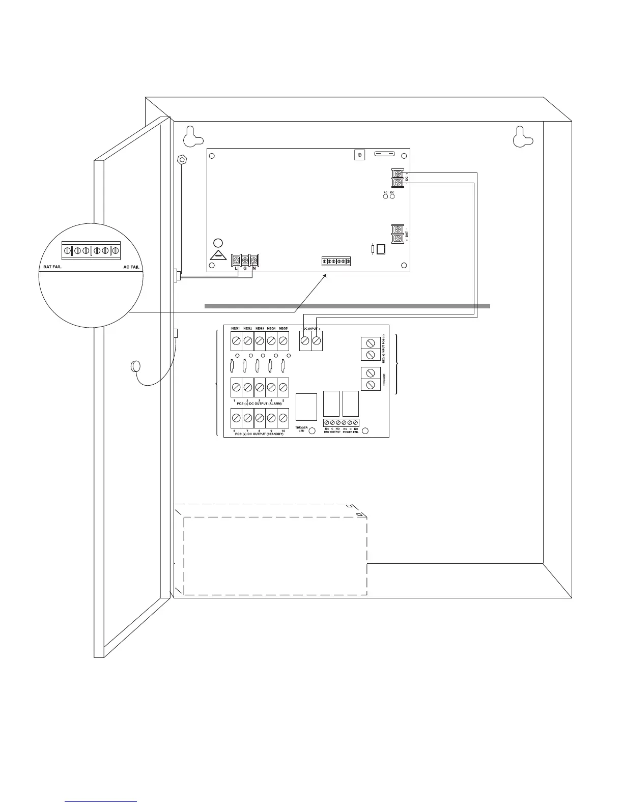
Fig. 2 - AL600ULM
- DC INPUT +
POS (+) DC OUTPUT (ALARM)
POS (+) DC OUTPUT (STANDBY)
6 7 8 9 10
1 2 3 4 5
TRIGGER
LED
POWER
ON LED
NEG1 NEG2 NEG3 NEG4 NEG5
TRIGGER
NC C NO NC C NO
DRY OUTPUT POWER FAIL
MOM5_S
- INPUT +
BAT FAIL NC C NO NC C NO AC FAIL
AC DC
BAT
+ BAT -
+ DC -
OFF - 24V
ON - 12V
ON
L G N
AC Delay
115VAC power mains
non power-limited
Earth
Ground
Class 1
Wire Strap
(from Enclosure
to Door)
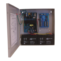
Optional Rechargeable
Stand-by Battery
Optional Rechargeable
Stand-by Battery
DC Outputs to devices
(power-limited)
Battery Connections
non power-limited
non power-limited
SW1
ON
1
OFF - 24V
ON - 12V
Battery & AC
Supervision Circuit
(power-limited)
NC C NO NC C NO
Keep power-limited wiring separate from non power-limited.
Use minimum 0.25" spacing.
CAUTION: Optional rechargeable stand-by batteries must match
the power supply output voltage setting.
CAUTION: De-energize unit prior to servicing. For continued protection
against risk of electric shock and fire hazard replace fuses with the same type
and rating (see marking on the board). Do not expose to rain or moisture.
J1
AC Delay
Fig. 2a
Fig. 2b
Fig. 2c
 Loading...