IPB-5000B
5. Installation and Connection
5-6
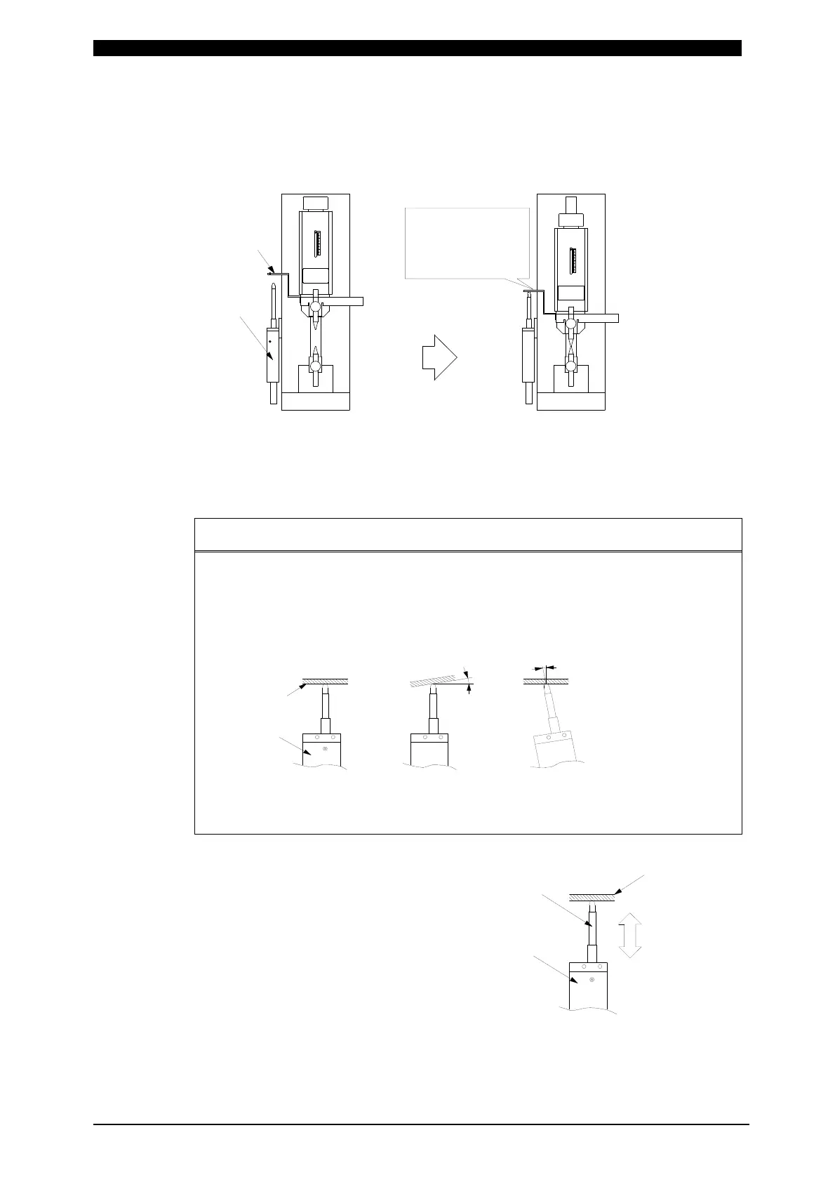
(8) Connecting Displacement Sensor (only for model with Sensor)
Install firmly Displacement Sensor not so as to rattle in reference to the figure
below.
Install Displacement Sensor with insulated.
When using the function of detecting a workpiece, adjust the installation
position of Sensor for the shaft of sensor so as to retract halfway in the
condition before the electrode is forced (left-side figure above).
ATTENTION
As the figure (A) below, be sure to keep Displacement Sensor perpendicular
to Displacement Detecting Plate.
If Displacement Sensor is slantingly installed like (B) or (C), the life of the
sensor becomes shorter.
θ
[Normal] [Abnormal]
θ
(A) (C)(B)
[Abnormal]
Displacement
Sensor
Displacement
Detecting
Plate
If Sensor is pressed beyond the range of measurement, it results in
malfunction.
The measured value of displacement is
minus (-) or plus (+).
When NORMAL is selected for
DISPLACEMENT POLARITY in the MISC
screen, the counted value is plus (+) in
the direction of retraction of the movable
part of Displacement Sensor and the
value is minus (-) in the extension.
On the other hand, when REVERSE is
selected, the counted value is minus (-) in
the direction of retraction of the movable
part of Displacement Sensor and the
value is plus (+) in the extension.
Displacement
Sensor
4
3
2
1
0
4
3
2
1
0
Adjust sensor so that
shaft of sensor
retracts halfway
when electrode is
at bottom.
(Before Forcing)
Displacement
Detecting
Plate
After Forcin
Retracting
Extending
Displacement
Detecting Plate
Shaft of
Sensor
Displacement
Sensor