Do you have a question about the Amada IS-800A-10 Series and is the answer not in the manual?
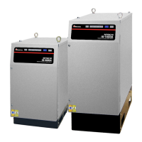
The AMADA WELD TECH IS-800A/1400A is a DC inverter welding power supply specifically designed for spot welding and fusing applications. It is characterized by its large capacity and compact size.
This power supply offers a welding-current monitoring function for weld quality judgment. It incorporates six control systems to ensure stable weld quality: Primary constant-current effective value control, Secondary constant-current effective value control, Secondary constant-power effective value control, Primary constant-current peak value control, Secondary constant-voltage effective value control, and Constant-phase control. These control methods can be independently set for WELD1 to WELD3. The device also supports pulsation and upslope/downslope settings for WELD1 to WELD3. A current-shutoff function is included, which activates in response to external input (e.g., electrode displacement) for WELD1 to WELD3, ensuring stable fusing. The inverter technology contributes to a high power factor and stable power conditions.
The IS-800A/1400A models offer different welding power inputs and maximum output currents. For the IS-800A-10-10/-10-12 and IS-800A-10-11/-10-13 models, the welding power is 3-phase, 380-480V AC ±10% (50/60 Hz) and 3-phase, 200-240V AC ±10% (50/60 Hz) respectively, with a maximum output current of 800 A (peak value). For the IS-1400A-10-10/-10-12 and IS-1400A-10-11/-10-13 models, the welding power is 3-phase, 380-480V AC ±10% (50/60 Hz) and 3-phase, 200-240V AC ±10% (50/60 Hz) respectively, with a maximum output current of 1400 A (peak value). The voltage level is factory-set and not field selectable. The average maximum duty cycle (at 40°C, 1 kHz welding frequency) for the 800A model is 3% at 800A, 10.5% at 500A, 20% at 350A, and 100% at 100A. For the 1400A model, it's 3% at 1400A, 7% at 1000A, 26% at 500A, and 100% at 100A. The device supports up to 255 welding schedules. Timer setting ranges for SQD (squeeze delay time), SQZ (squeeze time), UP (upslope time), WELD (weld time), DOWN (downslope time), COOL (cooling time), HOLD (hold time), and OFF (off time) vary, with maximums like 9999 ms for SQD/SQZ/COOL and 999 ms for UP/WELD/DOWN in ms mode, or 999 CYC and 50 CYC respectively in CYC mode. HOLD time can be up to 20000 ms or 999 CYC. The transformer turns ratio is adjustable from 1.0 to 199.9. The transformer frequency can be set from 600 Hz to 3000 Hz in units of 100 Hz. Pulsation settings are from 01 to 19 for WELD1 to WELD3. The unit supports 2 valves (VALVE1, VALVE2) and offers a control gain from 1 to 9. Current monitoring ranges from 0.00-9.99 kA to 00.0-99.9 kA, power monitoring from 00.00-99.99 kW to 000.0-999.9 kW, and voltage monitoring from 0.00-9.99 V. Pulse width monitoring is from 010.0-100.0%. Step-up/-down functions include 9 steps, with ratios from 50-200% and counter settings from 0000-9999. Weld count monitoring is from 0000-9999. Protective functions include overcurrent (200 A Fuse per unit), no-current, no-voltage, temperature (overheating), and self-diagnostic error. Setting accuracy is within ±3% of full scale, and repetition accuracy is within 4% of full scale (under specified conditions). The IS-800A has dimensions of 490 mm (H) x 280 mm (W) x 481 mm (D) and weighs 38 kg. The IS-1400A has dimensions of 658 mm (H) x 303 mm (W) x 489 mm (D) and weighs 60 kg. Both have an IP20 case protection rating. The operating environment should be +5 to +40°C, 90% max. humidity (no condensation), and an altitude of 1000 m max. Transportation and storage conditions are -10 to +55°C, 90% max. humidity (no condensation).
The power supply features an easy-to-use menu selection system for setting various parameters. It supports multiple languages: Japanese, English, Chinese, and Korean. The MA-660A Program Unit (sold separately) allows for setting weld schedules and monitoring results. Data can be copied between the MA-660A and the power supply, and between different power supply units with the same program version. The system allows for up to 255 welding schedules, which can be selected via schedule signals or directly from the MA-660A. The MONITOR screen displays operational conditions during welding, including time, current, voltage, power, and pulse width for each WELD operation. These values are stored for about 10 days even after power-off. The MONITOR SET screen allows users to define upper and lower limits for weld time, current, voltage, power, and pulse width to determine weld quality. If monitored values fall outside these limits, a caution signal is output. The NG SIGNAL SELECT screen configures the output mode and signal type (ERROR or CAUTION) for various error conditions, such as time-over, current-over, voltage-over, power-over, pulse-over, no-current, and work error. The OUTPUT SELECT screen allows assignment of various output signals (END, COUNT ERROR, READY, STEP END, WELD SIGNAL, GOOD, COUNT UP, OUT I, OUT II) to specific output pins. The MODE SELECT screen offers settings for delay start, start signal mode (Latched, Pulsed, Maintained, or binary/single signal starts), end signal time and mode, weld time units (ms or CYC), WELD STOP/PARITY CHECK, FLOW SWITCH/PRG PROTECT, STEPPER MODE (Fixed or Linear), SCHEDULE selection (External or Internal), VALVE MODE (1 or 2 Valve), RE-WELD function, COUNTER modes (Total, Good, Work), SCAN MODE, COMM CONTROL (Off, One-way, Both-way), COMM MODE (RS-485, RS-232C), and COMM SPEED. The MONITOR MODE screen allows setting of preset counters for total, good, or weld/work counts, and also configures no-current time/level, no-voltage level, monitor first time, and monitor slope mode. The STEPPER COUNT screen enables step-up (-down) operations for welding current based on the number of welds, with adjustable ratios and counts for up to 9 steps. The PRECHECK screen allows setting weld time and pulse width for resistance precheck welding, and defines upper and lower resistance limits for precheck.
The device includes a RESET key on the front panel and a TROUBLE RESET key on the MA-660A to clear error indications. The RESET TO DEFAULT screen allows initialization of the power supply's memory to restore initial settings. The PROGRAM PROTECT MODE screen prevents unauthorized changes to settings when activated. The I/O CHECK screen provides a status check of external I/O signals for troubleshooting. The manual provides a detailed fault code list with descriptions of causes and recommended measures for various errors, including system errors, memory errors, parity errors, external/internal thermo trips, lack of cooling water, start errors, frequency failures, out-of-limit errors (current, voltage, power, pulse width, time), interrupt errors, no voltage, DC24V overcurrent, short circuit, precheck errors, RAM memory errors, lack of weld count, end of step, count up, phase missing, and power failure. It also provides guidance on troubleshooting scenarios where welding does not start, including issues with the READY lamp, start signal timing, and communication with the MA-660A. A list of main control board, drive board, snubber board, display board, and fan motor assembly for repair or replacement is provided. Major components list includes fan motor, power transformer, thermal protector, diode module, IGBT module, fast-blow fuse, and electromagnetic contactor. The manual includes a schedule data table for reference of initial values for all settings.
| Brand | Amada |
|---|---|
| Model | IS-800A-10 Series |
| Category | Welding Accessories |
| Language | English |