SCHEDULED MAINTENANCE
28
Improper lter maintenance is the most common cause of
inadequate heating or cooling performance. Filters should
be cleaned (permanent) or replaced (disposable) every two
months or as required. It is the owner’s responsibility to keep
air lters clean. When replacing a lter, it must be replaced
with a lter of the same type and size.
Depending on the installation, diering lter arrangements
can be applied. Filters can be installed in the central return
register, the bottom of the blower compartment (upow
only), a side panel external lter rack kit (upow only), or the
ductwork above a counterow furnace. A media air lter or
electronic air cleaner can be used as an alternate lter. The
lter sizes given in the Product Design section of this manual
or the product Specication Sheet must be followed to ensure
proper unit performance. Refer to the following information
for removal and installation of lters.
Follow the manufacturer’s directions for service.
Filters in horizontal installations are located in the central
return register.
The bearings in the induced draft blower and circulator blower
motors are permanently lubricated by the manufacturer. No
further lubrication is required. Check motor windings for
accumulation of dust which may cause overheating. Clean
as necessary.
The drain tubes, standpipe, and eld supplied drain line must
be checked annually and cleaned as often as necessary to
ensure proper condensate drainage.
FLAME SENSOR (QUALIFIED SERVICER ONLY)
Under some conditions, the fuel or air supply can create a
nearly invisible coating on the ame sensor. This coating acts
as an insulator, causing a drop in the ame sensing signal. If
this occurs, a qualied servicer must carefully clean the ame
sensor with steel wool. After cleaning, the ame sensor output
should be as listed on the specication sheet.
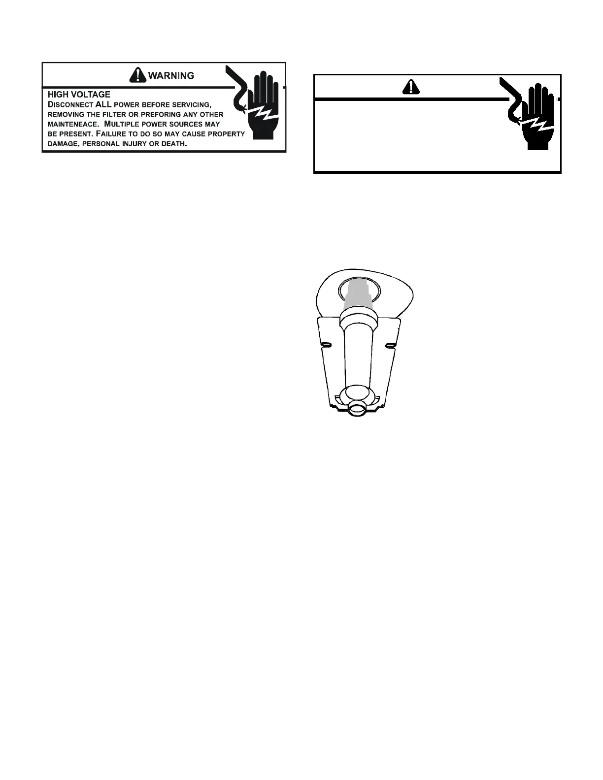
WARNING
IG
VLAGE
E
LECRICAL CMPNENS ARE CNAINED IN
CMPARMENS
AVID ELECRICAL SCK INJR R
DEA D N REMVE AN INERNAL CMPARMEN CVERS
R AEMP AN ADJSMEN
C
NAC A QALIIED
SERVICE AGEN A NCE I AN ANRMAL LAME
APPEARANCE SLD DEVELP
Periodically during the heating season make a visual check of
the burner ames. Turn the furnace on at the thermostat. Wait
a few minutes since any dislodged dust will alter the normal
ame appearance. Flames should be stable, quiet, soft and
blue with slightly orange tips. They should not be yellow. They
should extend directly outward from the burner ports without
curling downward, oating or lifting o the ports.
Proper test equipment for accurate diagnosis is as essential
as regular hand tools.
The following is a must for every service technician and
service shop.
1. Dial type thermometers or thermocouple meter (option-
al) - to measure dry bulb temperature.
2. Amprobe - to measure amperage and voltage.
3. Volt-Ohm Meter - testing continuity, capacitors, and
motor windings.
4. Inclined Manometer - to measure static pressure, pres-
sure drop across coils, lters, and draft.
5. Water Manometer (12”) - to test gas inlet and manifold
pressure.
Other recording type instruments can be essential in solving
abnormal problems, however, in many instances they may
be rented from local sources.
Proper equipment promotes faster, more ecient service and
accurate repairs resulting in fewer call backs.