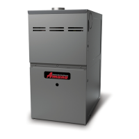
Do you have a question about the Amana AMH8 and is the answer not in the manual?
Critical safety and responsibility information for furnace installers.
Guidance for installers before starting work.
Procedures for inspecting the unit for damage upon arrival.
Steps to prevent damage to electronic components from static electricity.
Specifies approved applications and restrictions for the furnace.
General guidelines for selecting furnace location.
Specifies required clearances for servicing and safe operation.
Requirements for installing the furnace in a horizontal orientation.
Guidelines for suspending the furnace using threaded rods and angle iron.
Procedures and considerations when removing an old furnace.
Table specifying minimum vent pipe diameters based on furnace model.
Furnace is not certified for horizontal venting.
Summary of checks for venting into a masonry chimney.
Requirements for the chimney's height and termination point.
Verifying no solid or liquid fuel appliances share the chimney.
Inspecting the chimney crown for damage.
Inspecting the chimney cleanout for obstructions and debris.
Assessing the integrity and suitability of the chimney liner.
Ensuring sufficient dilution air is available for the venting system.
Final checks and considerations for completing the installation.
Options for altering venting if the original configuration is unsuitable.
Options and considerations for relining a chimney.
General warnings and requirements for electrical connections.
Information on the furnace's wiring harness and replacement wire specifications.
Guidelines for making 115-volt power supply connections.
Procedure for relocating the furnace's junction box.
Wiring diagrams for connecting a 24-volt thermostat.
Method to measure amp draw for setting the thermostat's heat anticipator.
Connecting accessories like electronic air cleaners to furnace power.
General requirements for gas supply and piping installation.
Adjustments for furnace operation at higher altitudes.
Alternative method for calculating altitude derating and orifice selection.
Requirements for connecting the gas piping to the furnace.
Procedures and kits required for propane conversion.
Specific piping requirements for upflow installation configurations.
Essential checks to perform on gas piping before operation.
Safety and installation considerations for propane gas storage and piping.
Design considerations for ductwork and register sizing for the furnace.
Importance of filters, their installation, and maintenance.
Steps involved when the furnace initially receives power.
Normal operational sequence for the furnace during heating.
Normal operational sequence for the furnace during cooling.
Step-by-step guide for safely starting up the furnace.
Step-by-step guide for safely shutting down the furnace.
Procedure for measuring and verifying the inlet gas supply pressure.
Procedure for measuring and adjusting the gas manifold pressure.
Method for measuring and verifying the natural gas input rate.
How to measure and adjust the temperature rise.
Instructions for adjusting the blower speed for heating and cooling.
Visual inspection guidelines for burner flame appearance and stability.
Adjustment of fan timing on models with optional delay pins/switches.
Description of the electronic control module and its diagnostic functions.
Function and location of the primary limit control.
Function and location of the auxiliary limit control.
Function and location of rollout limit controls.
Function of pressure switches monitoring airflow.
Function of the flame sensor for detecting flame presence.
Guide to interpreting diagnostic LED codes for troubleshooting.
Procedures for resetting the furnace after it enters lockout mode.
Recommended annual inspection points for furnace and system.
Guidelines for cleaning or replacing filters to maintain performance.
Procedures for removing filters from different installation types.
Cleaning and testing the flame sensor for proper function.
Checking the resistance of the igniter and when to replace it.
Visual inspection and cleaning procedures for furnace burners.
Final checks and homeowner orientation.
Information on ordering functional and sheet metal parts for the furnace.
A detailed chart to diagnose and resolve furnace operational problems based on LED codes.
The complete wiring diagram for the AMH8 furnace, showing all connections.
| Model | AMH8 |
|---|---|
| Type | Gas Furnace |
| Efficiency Rating | High Efficiency |
| Blower Type | Multi-Speed |
| AFUE | 80% |
| Stages | Single-Stage |
| Heat Exchanger Material | Stainless Steel |
| Ignition Type | Direct Spark Ignition |
| Heating Capacity | 40, 000 to 120, 000 BTU/h |
| Fuel Type | Natural Gas |
| Warranty | 10-Year Parts Limited Warranty |