16
12" MIN.
TO ROOF OR
HIGHEST
ANTICIPATED
SNOW LEVEL
90º
MEDIUM RADIUS
ELBOWS
Alternate Vertical Termination (Single Pipe)
MIN.
12"
FROM
WALL
12"
TO GROUND OR
HIGHEST ANTICIPATED
SNOW LEVEL
WALL
INSIDE
OUTSIDE
TEE
or
90°ELBOW
TURNED
DOWN
COUPLING
ELBOW OR
COUPLING
Horizontal Termination (Single Pipe)
VENT/FLUE TEE
or
90° ELBOW TURNED
DOWN
12" MIN.
Horizontal Termination (Single Pipe)
Above Highest Anticipated Snow Level
DIRECT VENT (DUAL PIPE) PIPING
The inlet air screens provided in the installation instruction packet
are available for the installer to use in the inlet of the combustion
air pipe to prevent animals from building nests in the combustion
air pipe. Installation of screens, while strongly recommended, is
not required and will not affect performance of the unit.
Direct vent installations require both a combustion air intake and
a vent/flue pipe. The pipes may be run horizontally and exit through
the side of the building or run vertically and exit through the roof of
the building. The pipes may be run through an existing unused
chimney; however, they must extend a minimum of 12 inches
above the top of the chimney. The space between the pipes and
the chimney must be closed with a weather tight, corrosion resis-
tant flashing. Both the combustion air intake and a vent/flue pipe
terminations must be in the same atmospheric pressure zone.
For details concerning connection of pipes to the furnace, refer to
the Section IX, Vent/Flue Pipe and Combustion Pipe - Standard
Furnace Connections or Alternate Furnace Connections.
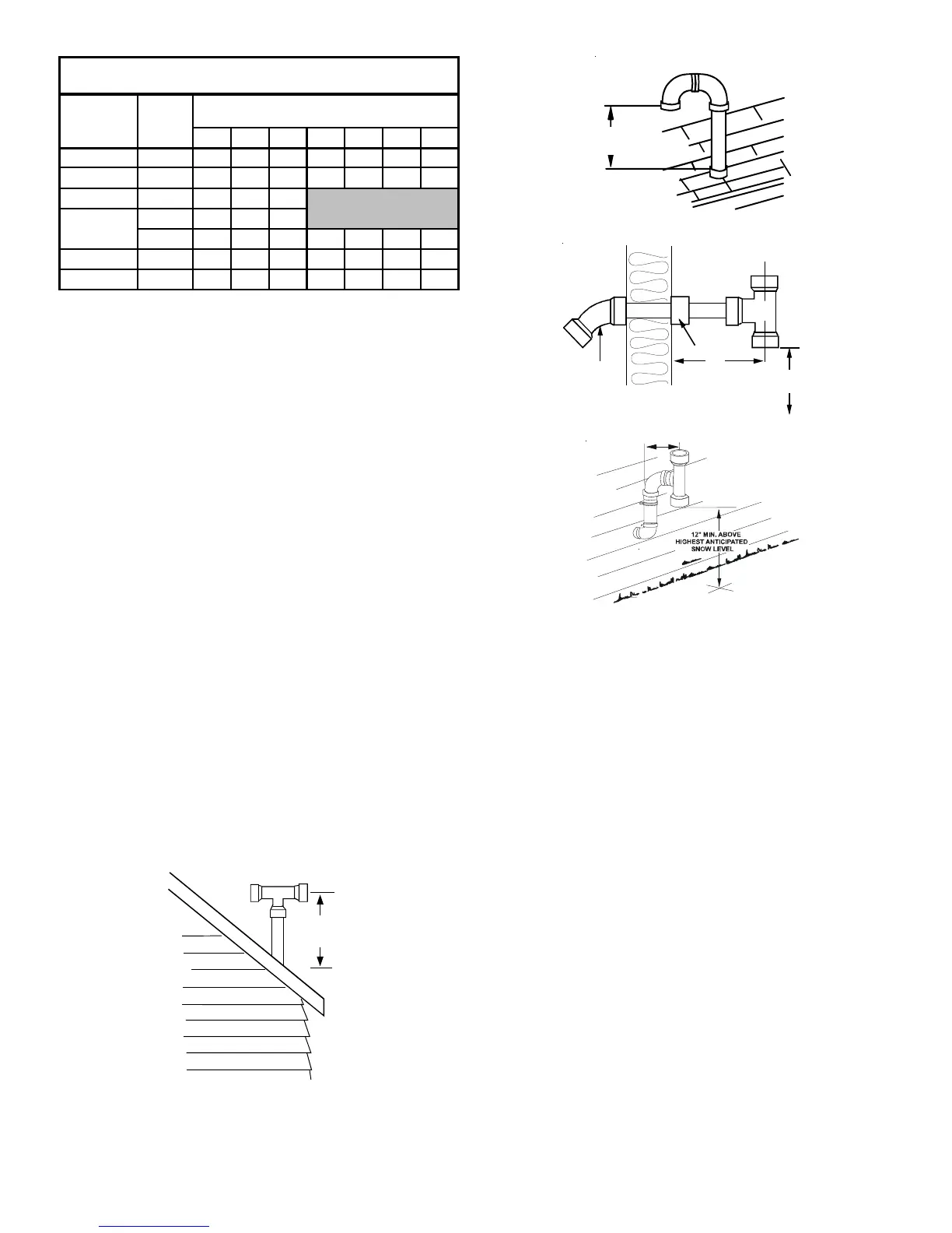
VENT/FLUE AND COMBUSTION AIR PIPE LENGTHS AND DIAMETERS
Refer to the following table for applicable length, elbows, and
pipe diameter for construction of the vent/flue and combustion air
intake pipe systems of a direct vent (dual pipe) installation. The
number of elbows tabulated represents the number of elbows
and/or tees in each (Vent/Flue & Combustion Air Intake) pipe.
Elbows and/or tees used in the terminations must be included
when determining the number of elbows in the piping systems.
Pipe
Size
(4)
(inc.)2345678
045_3 2 68 65 62 59 56 53 50
070_3 2 68 65 62 59 56 53 50
070_4 2 46 43 40
2161310
3 68656259565350
090_5 3 68 65 62 59 56 53 50
115_5 3 68 65 62 59 56 53 50
Non-Direct Vent (Single Pipe)
Maximum Allowable Length of Vent/Flue Pipe (ft)
(1) (2)
Number of Elbows
(3) (5)
Models
(kBtu_Tons)
090_4
Not Recommended
1) One 90° elbow should be secured to the combustion air intake con-
nection.
2) Minimum requirement for each vent pipe is five (5) feet in length and
one elbow/tee.
3) Tees and/or elbows used in the vent/flue termination must be included
when determining the number of elbows in the piping system.
4) 3” diameter pipe can be used in place of 2” diameter pipe.
5) Increased Clearance Configurations using (2) 45 deg.
Long Sweep
elbows should be considered equivalent to one 90 deg. elbow.
VENT/FLUE PIPE TERMINATIONS
The vent/flue pipe may terminate vertically, as through a roof, or
horizontally, as through an outside wall.
Vertical vent/flue pipe terminations should be as shown in the
following figure. Refer to Section IX, Vent/Flue Pipe and Com-
bustion Air Pipe - Termination Locations for details concerning
location restrictions. The penetration of the vent through the roof
must be sealed tight with proper flashing such as is used with a
plastic plumbing vent.
Horizontal vent/flue pipe terminations should be as shown in the
following figure. Refer to Section IX, Vent/Flue Pipe and Combus-
tion Air Pipe - Termination Locations for details concerning loca-
tion restrictions. A 2 3/8” diameter wall penetration is required for
2” diameter pipe while a 3 1/2” diameter hole is required for 3”
diameter pipe. To secure the pipe passing through the wall and
prohibit damage to piping connections, a coupling should be in-
stalled on either side of the wall and solvent cemented to a length
of pipe connecting the two couplings. The length of pipe should
be the wall thickness plus the depth of the socket fittings to be
installed on the inside and outside of the wall. The wall penetra-
tion should be sealed with silicone caulking material.
In a basement installation, the vent/flue pipe can be run between
joist spaces. If the vent pipe must go below a joist and then up
into the last joist space to penetrate the header, two 45° elbows
should be used to reach the header rather than two 90° elbows.
12 " Min To
Roof Or
Highest Anticipated
Snow Level
TEE
Vertical Termination (Single Pipe)
 Loading...