EasyManua.ls Logo

Amana ARUF49C14 Series - User Manual

Amana ARUF49C14 Series
24 pages
Print Icon
To Next Page IconTo Next Page
Loading...
RECOGNIZE THIS SYMBOL
AS A SAFETY PRECAUTION.
ATTENTION INSTALLING PERSONNEL
Prior to installation, thoroughly familiarize yourself with this Installation Manual.
Observe all safety warnings. During installation or repair, caution is to be observed.
It is your responsibility to install the product safely and to educate the customer on its safe use.
ARUF**14** / ASPT**14**
1 Important Safety Instructions
The following symbols and labels are used throughout this
manual to indicate immediate or potential safety hazards.
It is the owner’s and installer’s responsibility to read and
comply with all safety information and instructions accom-
panying these symbols. Failure to heed safety information
increases the risk of personal injury, property damage, and/
or product damage.
AIR HANDLERS INSTALLATION & OPERATING INSTRUCTIONS
IO-901
2/2015
Keep this literature in a safe place for future reference.
1 Important Safety Instructions...................................1
2 Shipping Inspection ............................................... 3
2.1 Parts .......................................................... 3
2.2 Handling ...................................................... 3
3 Codes & Regulations ..............................................3
4 Replacement Parts ................................................3
5 Pre-Installation Considerations ................................ 3
5.1 Preparation .................................................. 3
5.2 System Matches ............................................. 3
5.3 Interconnecting Tubing..................................... 3
5.4 Clearances ................................................... 4
5.5 Horizontal Applications .................................... 4
6 Installation Location .............................................4
6.1 Upflow Installation ......................................... 4
6.2 Horizontal Left Installation ............................... 4
6.3 Downflow..................................................... 4
6.4 Horizontal Right Installation.............................. 5
7 Refrigerant Lines .................................................. 7
7.1 Tubing Size ................................................... 7
7.2 Tubing Preparation ......................................... 7
7.3 Special Instructions......................................... 7
7.4 Tubing Connections for Flowrator Model ............... 7
7.5 Tubing Connections for TXV Models ...................... 8
8 Condensate Drain Lines .......................................... 8
9 Ductwork............................................................ 9
9.1 Return Ductwork ............................................ 9
10 Return Air Filters ................................................9
11 Electric Heat......................................................9
12 Electrical and Control Wiring ............................... 11
12.1 Building Electrical Service Inspection................ 11
12.2 Wire Sizing ............................................... 11
12.3 Maximum Overcurrent Protection (MOP) ............ 11
12.4 Electrical Connections – Supply Voltage ............. 12
12.4.1 Air Handler Only (Non-Heat Kit Models) ..... 12
12.4.2 Air Handler - Non-Circuit Breaker Heat Kits......12
12.4.3 Air Handler With Circuit Breaker Heat Kit........ 12
12.5 Low Voltage Connections............................... 12
12.5.1 Thermostats .......................................... 12
12.6 Speed Tap Adjustment .................................. 12
13 Achieving 1.4% Low Leakage Rate ......................... 13
14 Start-Up Procedure............................................ 13
15 Regular Maintenance.......................................... 13
16 Airflow Data .................................................... 14
21 Wiring Diagrams................................................ 20
Contents
Question and Answer IconNeed help?

Do you have a question about the Amana ARUF49C14 Series and is the answer not in the manual?

Summary

Important Safety Instructions

Safety Warnings and Hazards

High Voltage and Electrical Hazards

Warnings about high voltage, grounding, and electrical shock risks during operation and servicing.

Installation and Servicing Personnel Safety

Specifies technician qualifications and the need for protective gear during installation and repair.

Operational Safety Precautions

Covers warnings on power supply, approved devices, flammable materials, and carbon monoxide poisoning.

Pre-Installation Considerations

Installation Location

Refrigerant Lines

Condensate Drain Lines

Ductwork

Electric Heat

Electrical and Control Wiring

Wiring Routing, Service Inspection, Wire Sizing, and MOP

Covers wiring routing, service inspection, wire sizing criteria, and maximum overcurrent protection.

Supply Voltage Electrical Connections

Details connecting power supply for various configurations including heat kits.

Low Voltage Connections and Speed Tap Adjustment

Discusses low voltage wiring, thermostat connections, and blower speed tap adjustments.

Unit Leakage and Start-Up

Regular Maintenance

Air Handler Low Voltage Connections

Single-Stage Cooling and Heat Pump Wiring

Details wiring for cooling, heat pump, and thermostat configurations with outdoor thermostat options.

Electronic Blower Time Delay Relay

Wiring Diagrams Overview

ARUF**14** Model Wiring Diagram

Provides the detailed wiring diagram for the ARUF**14** model, including component codes and safety notes.

High Voltage Electrical Safety

Reinforces high voltage warnings and precautions for electrical work on the unit.

ASPT**14** and Heat Kit Wiring Diagrams

ASPT**14** Unit Wiring Diagram

Presents the wiring diagram for the ASPT**14** model with component and color codes.

Overview

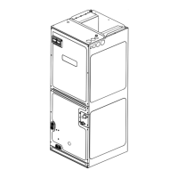
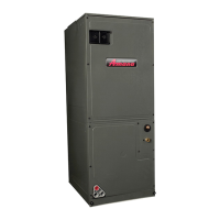
This document provides comprehensive installation and operating instructions for the ARUF14 and ASPT14 series air handlers. These units are designed for indoor installation only and are compatible with various heating and cooling systems.

Function Description:

The ARUF14 and ASPT14 air handlers are integral components of split heating and cooling systems, responsible for circulating conditioned air throughout a building. They are designed to work with remote cooling or heat pump outdoor units and can be equipped with optional electric heat kits for supplemental heating. The units facilitate refrigerant expansion (either via a flowrator piston or a factory-installed TXV), manage condensate drainage, and provide airflow for heating and cooling cycles. They are designed for flexible installation in upflow, downflow, horizontal left, or horizontal right orientations, with minor field modifications required for certain configurations.

Important Technical Specifications:

  • Electrical Power Supply: Factory-shipped for 208/240/1/60 electrical power supply. Reconfiguring for other power supplies is not permitted.
  • Refrigerant: Factory-shipped with R410A and dry nitrogen mixture gas under pressure.
  • Condensate Drain Connections: Primary and secondary drains with 3/4" NPT female connections. Torque for connections should not exceed 37 in-lbs.
  • Airflow: Designed to accommodate 350-450 CFM per ton of cooling with static pressure not exceeding 0.5" in w.c.
  • Filter Sizes (for factory filter rails):
    • B cabinet: Nominal 16x20x1"
    • C cabinet: Nominal 20x20x1"
    • D cabinet: Nominal 24x20x1" (Actual dimensions must be less than 23-1/2"x20")
  • Electrical Wiring: Copper conductors only. Minimum 18AWG for low voltage wiring up to 100 feet. Supply voltage must be within the range of 197-253V for a nominal 208-240V input.
  • Leakage Rate: Achieves less than 1.4% airflow leakage when tested in accordance with ASHRAE Standard 193, provided all gaskets are intact and panels are flush.
  • Blower Motor (ARUF14**):** Multi-speed PSC motors. Speed is determined by the color of the wire connected to the "COM" terminal (Black: high, Blue: medium, Red: low).
  • Blower Motor (ASPT14**):** Energy-efficient blower motors that run at constant torque, energized by 24 VAC. CFM is adjusted by changing 24 VAC leads to the desired speed tap.
  • Blower Time Delay Relay:
    • Normal Turn On Delay (60Hz): 7.0 SEC.±1%
    • Normal Turn Off Delay (60Hz): 65.0 SEC.±1%
    • Field Test Mode Turn On Delay (60Hz): 3.0 SEC.±1%
    • Field Test Mode Turn Off Delay (60Hz): 5.0 SEC.±1%

Usage Features:

  • Installation Flexibility: Can be installed in upflow, downflow, horizontal left, or horizontal right configurations.
  • Refrigerant Line Connections: Instructions provided for both flowrator piston and TXV models, including specific torque settings for connections and brazing procedures.
  • Condensate Management: Features primary and secondary drain connections. A "P" style trap is required for proper drainage, and insulation of drain lines is recommended to prevent sweating. A secondary drain pan is mandatory for installations above finished living spaces or where condensate overflow could cause damage.
  • Ductwork: Designed for a complete supply and return ductwork system. Ductwork must be flame retardant, sealed to prevent leakage, and sized according to ACCA Manual D, S, and RS.
  • Return Air Filters: Each installation requires a return air filter, which can be installed at the air handler using factory filter rails or externally.
  • Electric Heat Compatibility: Supports HKS series electric heat kits, which must be field installed. Temperature rise calculations are provided based on system airflow, supply voltage, and heat kit size.
  • Low Voltage Connections: Detailed wiring diagrams are provided for various configurations, including single-stage cooling, heat pump, and single or two-stage electric heating, with optional outdoor thermostat connections.
  • Speed Tap Adjustment: ARUF14 models allow manual adjustment of blower speed by swapping wires on the control board. ASPT14 models allow CFM adjustment via 24 VAC leads on the terminal block.

Maintenance Features:

  • Filter Replacement/Cleaning: The only user-required maintenance is regular cleaning or replacement of the circulating air filter(s), typically once per month.
  • Professional Servicing: All other services should be performed by a certified service technician. Bi-annual maintenance checkups by a qualified servicer are strongly recommended before heating and cooling seasons.
  • Coil Cleaning: Aluminum indoor coils can be flushed with water or cleaned with approved chemical cleaners (EVAP-Green, Extreme Simply Green, Aircraft Precision Cleaner). Outdoor coils should be cleaned by a qualified servicer to prevent damage.
  • Pre-Startup Checklist: Before startup, ensure all electrical wires are properly sized and tightened, panels are secured, tubing is leak-free, condensate line is trapped and pitched, low voltage wiring is connected, auxiliary drain is installed (if necessary), and the unit is protected from physical damage.
  • Troubleshooting Guide: Includes a "Before Calling Your Servicer" section with a checklist for common issues like thermostat settings, tripped circuit breakers, obstructions, and dirty filters.
  • Safety Precautions: Emphasizes disconnecting all power before servicing, using appropriate safety tools, and adhering to all warnings regarding high voltage, carbon monoxide poisoning, and proper grounding.

Amana ARUF49C14 Series Specifications

General IconGeneral
ModelARUF49C14
SeriesARUF
TypeAir Handler
Voltage208/230
Phase1
Maximum External Static Pressure (in. w.c.)0.5
Airflow (CFM)1600
Blower TypeMulti-speed
RefrigerantR-410A
Cooling Capacity (BTU/h)49000

Related product manuals