This document provides installation and operational instructions for a packaged terminal air conditioner/heat pump, designed for professional installers and end-users. It emphasizes safety precautions, proper installation procedures, and maintenance guidelines to ensure optimal performance and longevity of the unit.
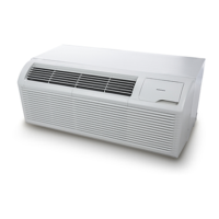
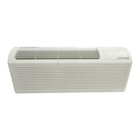
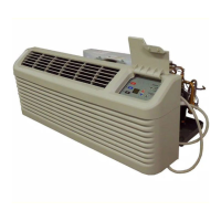
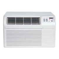
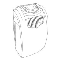
The device functions as a packaged terminal air conditioner and heat pump, offering both cooling and heating capabilities. It is designed to provide climate control for individual rooms or zones, making it suitable for various applications such as hotels, motels, and multi-family dwellings. The unit features a user-friendly control panel with buttons for mode selection, fan speed adjustment, power on/off, and set point temperature control. LED indicators provide visual feedback on the unit's operating status, including selected fan speed (HIGH, MED, LOW) and active mode (FAN, COOL, HEAT). A green LED indicates when the unit is powered ON.
One of the key usage features is the Memory function. In the event of a power loss, the unit retains all control settings, including mode, fan speed, on/off status, and configuration. When power is restored, the unit automatically resumes operation in the last saved mode and configuration, ensuring continuous comfort without needing to reconfigure settings.
The unit incorporates Automatic Evaporator Freeze Protection. This feature automatically turns off the compressor and activates the indoor fan if the evaporator temperature drops too low, preventing ice buildup and potential damage. The function deactivates once the evaporator temperature returns to a safe level.
For heat pump models, an Automatic Quick Warm-Up feature is included. If the room temperature falls significantly below the set point temperature (4.5°C / 8°F), the reverse cycle heat is temporarily shut off, and the electric strip heat engages for one cycle until the desired heating temperature is achieved. This ensures rapid heating when needed.
LED Indicators and Buttons on the touch pad allow for intuitive control. Users can select between COOL, HEAT, and FAN modes. In COOL mode, the unit automatically cools when the room temperature exceeds the set point and stops when it falls 2°C (4°F) below the set point, with a minimum compressor run time of 5 minutes. In HEAT mode, the maximum temperature can be set up to 29°C (84°F). Heat pump models can alternate between reverse cycle heat and electric heater modes based on the temperature difference between the set point and room temperature. The fan motor cycles with the compressor in HEAT mode. The FAN mode allows for fan operation only, without heating or cooling.
The FAN (FAN SPEED) button cycles through HIGH, MED, and LOW fan speed settings. A CONSTANT FAN function is available in cooling mode, which, when activated, keeps the fan running continuously, indicated by an illuminated light. When deactivated, the fan cycles on and off with the compressor.
The unit also supports DIP Switches Configurations for advanced settings. These switches, located behind the front panel, allow for customization of various parameters, including wall thermostat type, load delay, heating type, temperature display type (°F or °C), control type, setpoint limits, fan continuous run/cycle for heating and cooling, and low temperature protection. These configurations enable the unit to be tailored to specific installation requirements and user preferences. For instance, the Wall Thermostat Enable switch allows a wired wall thermostat to control the unit, while the Low Temperature Protection feature activates the fan motor and electric strip heat if the room temperature drops below 0°C (32°F), warming the room to 4.4°C (40°F).
High Temperature Protection in heating operation is a critical safety feature. It automatically switches off the compressor and/or electric heater to prevent damage from excessively high indoor blow air temperatures or errors in the indoor temperature sensor.
The DIP Switches Configurations by Panel Control offers an alternative method to adjust these settings directly from the control panel. By pressing and holding the up (+) and down (-) buttons simultaneously for 3 seconds, users can access and modify dip switch settings, with the LED display window showing two-digit codes for high (left) and low (right) functions.
Compressor Restart Delay is a feature designed to extend the compressor's lifespan by preventing short-cycling. When the compressor restarts, there is a minimum three-minute delay to allow refrigerant pressures to equalize, optimizing the cycling process.
For maintenance, the manual emphasizes the importance of regular cleaning. Air Filters should be cleaned every two weeks to maintain unit efficiency, reduce operating costs, save energy, prevent clogged indoor coils, and minimize the risk of premature component failure. Cleaning involves vacuuming heavy soil and rinsing with water. The Vent Door Filter also requires cleaning twice a year or as needed, especially if the vent door is open. The Outdoor Coil should be checked regularly for dirt buildup and professionally cleaned if clogged.
The manual also includes a Troubleshooting section to address common issues such as the unit not starting, inadequate cooling/heating, strange display numbers, and unusual noises. It provides solutions like checking power connections, resetting circuit breakers, cleaning filters, and verifying dip switch settings. For instance, if ice or frost forms on the indoor coil, it suggests checking the outdoor temperature and cleaning filters. If the compressor is in restart protection, a random startup delay of 3 minutes is normal.
Overall, the device is designed for efficient and reliable climate control, with features aimed at user convenience, energy efficiency, and product longevity, supported by clear installation and maintenance guidelines.