15
NOTE: Adjusting the minimum supply pressure below the
limits in the above table could lead to unreliable ignition. Gas
input to the burners must not exceed the rated input shown
on the rating plate. Overring of the fur nace can result in
premature heat exchanger failure. Gas pressures in excess
of 13 inch es water column can also cause permanent damage
to the gas valve.
At all altitudes, the manifold pressure must be within 0.3 inches
w.c. of that listed in the Specication Sheet applicable to your
model for the fuel used. At all altitudes and with either fuel,
the air tempera ture rise must be within the range listed on the
furnace nameplate. Should this appliance be converted to
LP, refer to the instructions included in the factory authorized
LP conversion kit.
high Altitude derAte
High altitude installations may require both a pressure switch
and an orice change. These changes are necessary to com-
pensate for the natural reduction in the density of both the gas
fuel and the combustion air at higher altitude.
Clearance in accordance with local installation codes, the
requirements of the gas supplier and the manufacturer’s
installation instructions.
Dégaugement conforme aux dodes d’installation locaux, aux
exigences du fournisseur de gaz et aux instructions d’instal-
lation du fabricant.
#45
3.5" w.c. 1.9" w.c. None
#55 10.0" w.c. 6.0" w.c. None
#55 10.0" w.c. 6.0" w.c. None
NOTE: In Canada, gas furnaces are only certified to 4500 feet.
Consult the furnace Specication Sheet for appropriate manu-
facturer’s kits for propane gas and/or high altitude installations.
The indicated kits must be used to insure safe and proper
furnace operation. All conversions must be performed by a
qualied installer, or service agency.
propAne gAS ConverSion
WARNING
P
OSSIBLE
PROPERTY
DAMAGE
,
PERSONAL
INJURY
OR
DEATH
MAY
OCCUR
IF
THE
CORRECT
CONVERSION
KITS
ARE
NOT
INSTALLED
. T
HE
APPROPRIATE
KITS
MUST
BE
APPLIED
TO
ENSURE
SAFE
AND
PROPER
FURNACE
OPERATION
. A
LL
CONVERSIONS
MUST
BE
PERFORMED
BY
A
QUALIFIED
INSTALLER
OR
SERVICE
AGENCY
.
This unit is congured for natural gas. The appropriate man-
ufacturer’s propane gas conversion kit must be applied for
propane gas installations.
If converting to LP gas, it is recommended that an LPLP0* kit
also be installed. The use of this kit will prevent the furnace
from ring when the LP gas supply pressure is too low to
support proper combustion.
gAS piping ConneCtionS
T
O
AVOID
POSSIBLE
UNSATISFACTORY
OPERATION
OF
EQUIPMENT
DAMAGE
DUE
TO
UNDERFIRING
OR
EQUIPMENT
,
USE
THE
PROPER
SIZE
OF
NATURAL
/
PROPANE
GAS
PIPING
NEEDED
WHEN
RUNNING
PIPE
FROM
THE
METER
/
TANK
TO
THE
FURNACE
.
WARNING
When sizing gas lines, be sure to include all appliances which
will operate simultaneously.
The gas piping supplying the furnace must be properly sized
based on the gas ow required, specic gravity of the gas,
and length of the run. The gas line installation must comply
with local codes, or in their absence, with the latest edition of
the National Fuel Gas Code, NFPA 54/ANSI Z223.1.
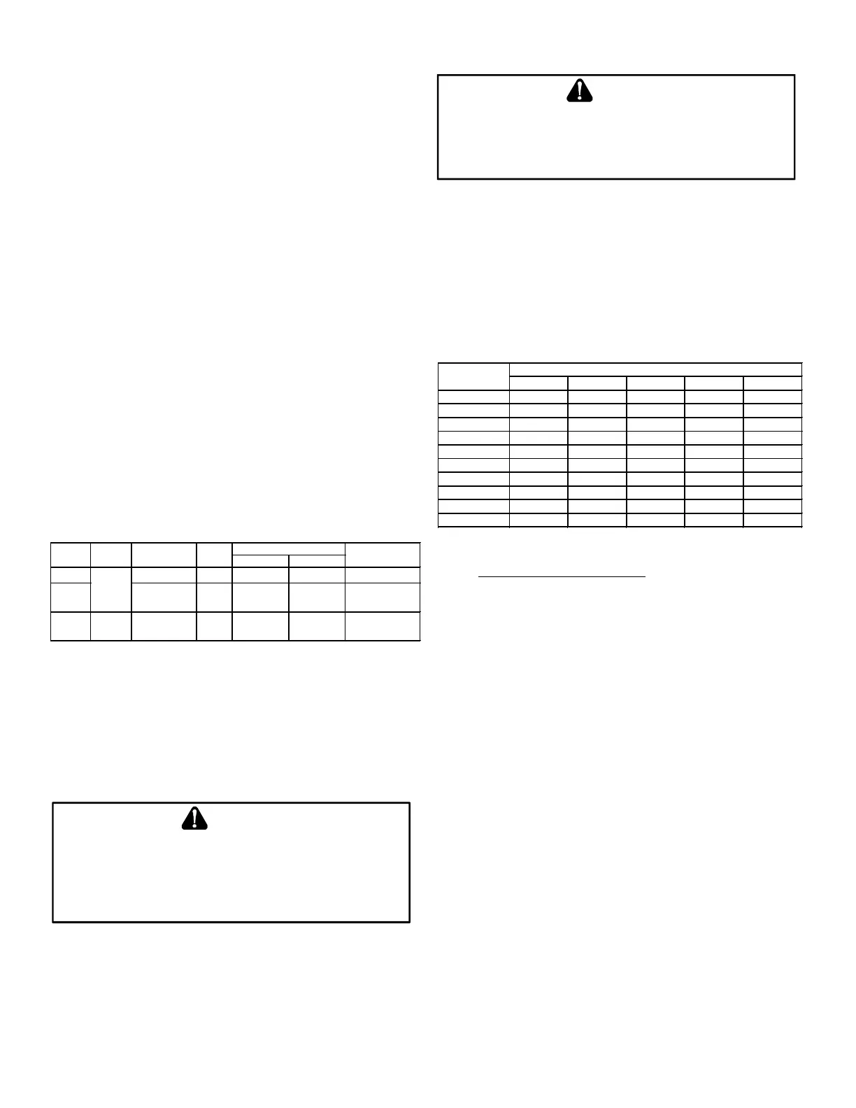
Natural Gas Capacity of Pipe
In Cubic Feet of Gas Per Hour (CFH)
Length of Nominal Black Pipe Size
Pipe in Feet 1/2" 3/4"
1" 1 1/4" 1 1/2"
10 132 278 520 1050 1600
20 92 190 350 730 1100
30 73 152 285 590 980
40 63 130 245 500 760
50 56 115 215 440 670
60 50 105 195 400 610
70 46 96 180 370 560
80 43 90 170 350 530
90 40 84 160 320 490
100 38 79 150 305 460
(Pressure 0.5 psig or less and pressure drop of 0.3" W.C.; Based on
0.60 Specific Gravity Gas)
BTUH Furnace Input
Heating Value of Gas (BTU/Cubic Foot)
To connect the furnace to the building’s gas piping, the install-
er must supply a ground joint union, drip leg, manual shutoff
valve, and line and ttings to connect to gas valve. In some
cases, the installer may also need to supply a transition piece
from 1/2” pipe to a larger pipe size.
The following stipulations apply when connecting gas piping.
• Gas piping must be supported external to the furnace
cabinet so that the weight of the gas line does not
distort the burner rack, manifold or gas valve.
• Use black iron or steel pipe and ttings for the building
piping.
• Use pipe joint compound on male threads only. Pipe
joint compound must be resistant to the action of the
fuel used.
• Use ground joint unions.
• Install a drip leg to trap dirt and moisture before it can
enter the gas valve. The drip leg must be a minimum
of three inches long.
• Use two pipe wrenches when making connection to
the gas valve to keep it from turning. The orientation
of the gas valve on the manifold must be maintained
as shipped from the factory.
 Loading...