25
To connect an electronic air cleaner using the line voltage
EAC terminal:
• Turn OFF power to the furnace before installing any
accessories.
• Follow the air cleaner manufacturers’ instructions
for locating, mounting, grounding, and controlling
accessories. Utilize 1/4” quick connect terminals to
make accessory wiring connections to the furnace
integrated control module.
• Connect the hot terminal utilized for accessory
operation to the EAC terminal and the neutral side
of power to NEUTRAL bus on the integrated furnace
control or the neutral connection in the furnace
junction box.
• All eld wiring must conform to applicable codes.
• If it is necessary for the installer to supply additional
line voltage wiring to the inside of the furnace, the
wiring must conform to all local codes, and have a
minimum temperature rating of 105°C.
• All line voltage wire splices must be made inside the
furnace junction box.
StartuP ProCedure & adjuStment
Furnace must have a 115 VAC power supply properly connected
and grounded. Proper polarity must be maintained for correct
operation. In addition to the following start-up and adjustment
items, refer to further information in Operational Checks section.
drAin trAp priming
The drain trap MUST be primed prior to furnace startup. To
prime, ll both sides of the drain trap with water. This ensures
proper furnace drainage upon startup and prohibits the possi-
bility of ue gases escaping through the drain system.
furnACe operAtion
Purge gas lines of air prior to startup. Be sure not purge lines into
an enclosed burner compartment. Follow NFPA 54, National
Fuel Gas Code for proper purging methods. In Canada, follow
approved purging methods in CAN/CSA B149.1-15.
Check for leaks using an approved chloride-free soap and
water solution, an electronic combustible gas detector, or other
approved method. Verify that all required kits (propane gas,
high altitude, etc.) have been appropriately installed.
furnACe StArtup
1. Close the manual gas shutoff valve external to the furnace.
2. Turn off the electrical power to the furnace.
3. Set the room thermostat to the lowest possible setting.
4. Remove the burner compartment door.
NOTE: This furnace is equipped with an ignition device which
automatically lights the burner. Do not try to light the burner
by hand.
OFF
100% CFM 100% CFM
1 min
OFF
Figure 28
• Prole B (2) ramps up to full cooling demand airow
by rst stepping up to 50% of the full demand for 30
seconds. The motor then ramps to 100% of the required
airow. A one (1) minute OFF delay at 100% of the
cooling airow is provided.
50% CFM
1/2 min
100% CFM
100% CFM
1 min
OFF
OFF
Figure 29
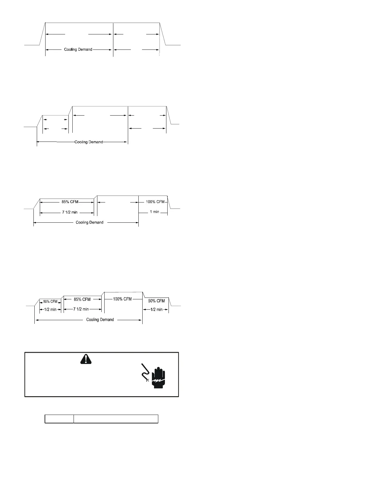
• Prole C (3) ramps up to 85% of the full cooling demand
airow and operates there for approximately 7 1/2
minutes. The motor then steps up to the full demand
airow. Prole C also has a one (1) minute 100% OFF
delay.
Figure 30
• Prole D (4) ramps up to 50% of the demand for 1/2
minute, then ramps to 85% of the full cooling demand
airow and operates there for approximately 7 1/2
minutes. The motor then steps up to the full demand
airow. Prole D has a 1/2 minute at 50% airow OFF
delay.
Figure 31
115 volt line ConneCtion or eleCtroniC Air CleAner
TO AVOID
PERSONAL INJURY OR DEATH, DUE TO
ELECTRICAL SHOCK, DISCONNECT ELECTRICAL POWER
BEFORE SERVICING OR CHANGING ANY ELECTRICAL
WIRING.
WARNING
EAC 1.0 AMP maximum at 120 VAC
The furnace integrated control module is equipped with a line
voltage accessory terminal for controlling power to an option-
al eld supplied electronic air cleaner or any device required
to operate inparallel with a circulating fan demand.
 Loading...