29
for heat was a call for high heat, the air cirulating
motor will run on the high heating speed for thirty (30)
seconds and then switch to the low heating spped for
the reminder of the heat off delay period.
• Circulator blower and electronic air cleaner terminal
are de-energized.
• Circulator blower shuts off after the heat off delay
period expires.
• Furnace awaits next call from thermostat.
oPerational CheCkS
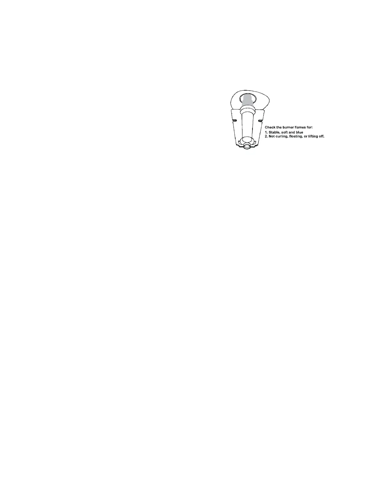
The burner ames should be inspected with the burner compart-
ment door installed. Flames should be stable, quiet, soft, and blue
(dust may cause orange tips but they must not be yellow). Flames
should extend directly outward from the burners without curling,
oating, or lifting off. Flames must not impinge on the sides of the
heat exchanger ring tubes.
Safety CirCuit deSCriPtion
A number of safety circuits are employed to ensure safe and proper
furnace operation. These circuits serve to control any potential
safety hazards and serve as inputs in the monitoring and diagnosis
of abnormal function. These circuits are continuously monitored
during furnace operation by the integrated control module.
integrAted Control module
The integrated control module is an electronic device which, if
a potential safety concern is detected, will take the necessary
precautions and provide diagnostic information through an LED.
primAry limit
The primary limit control is located on the partition panel and
monitors heat exchanger compartment temperatures. It is
a normally-closed (electrically), automatic reset, tempera-
ture-activated sensor. The limit guards against overheating
as a result of insufcient conditioned air passing over the
heat exchanger.
AuxiliAry limit
The auxiliary limit controls are located on or near the circulator
blower and monitors blower compartment temperatures. They are
a normally-closed (electrically), manual-reset sensors. These limits
guard against overheating as a result of insufcient conditioned
air passing over the heat exchanger.
rollout limit
The rollout limit controls are mounted on the burner/manifold as-
sembly and monitor the burner ame. They are normally-closed
(electrically), manual-reset sensors. These limits guard against
burner ames not being properly drawn into the heat exchanger.
Pressure Switches.
preSSure SwitCheS
The pressure switches are normally-open (closed during operation)
negative air pressure-activated switches. They monitor the airow
(combustion air and ue products) through the heat exchanger
via pressure taps located on the induced draft blower and the
coil front cover. These switches guard against insufcient airow
(combustion air and ue products) through the heat exchanger
and/or blocked condensate drain conditions.
flAme SenSor
The ame sensor is a probe mounted to the burner/manifold as-
sembly which uses the principle of ame rectication to determine
the presence or absence of ame.
Burner Flame
Figure 35
troubleShooting
eleCtroStAtiC diSChArge (eSd) preCAutionS
NOTE: Discharge body’s static electricity before touching
unit. An electrostatic discharge can adversely affect
electrical components.
Use the following precautions during furnace installation
and servicing to protect the integrated control module
from damage. By putting the furnace, the control, and
the person at the same electrostatic potential, these steps
will help avoid exposing the integrated control module to
electrostatic discharge. This procedure is applicable to both
installed and uninstalled (ungrounded) furnaces.
1. Disconnect all power to the furnace. Do not touch the
integrated control module or any wire connected to the
control prior to discharging your body’s electrostatic charge
to ground.
2. Firmly touch a clean, unpainted, metal surface of the
furnace away from the control. Any tools held in a
person’s hand during grounding will be discharged.
3. Service integrated control module or connecting
wiring following the discharge process in step 2. Use
caution not to recharge your body with static electricity;
(i.e., do not move or shufe your feet, do not touch
ungrounded objects, etc.). If you come in contact with
an ungrounded object, repeat step 2 before touching
control or wires.
4. Discharge your body to ground before removing a new
control from its container. Follow steps 1 through 3 if
installing the control on a furnace. Return any old or
new controls to their containers before touching any
ungrounded object.
 Loading...