7
CleArAnCeS And ACCeSSibility
Unobstructed front clearance of 24” for servicing is recom-
mended.
TOP
B1-VENT SINGLE
(PLENUM)
1" 6" 1" 3" 0" 1"
Top clearance for horizontal conguration - 1”
inStAllAtion poSitionS
*MVC80 model furnaces may be installed vertically (upow) or
horizontally with left or right side down. *CVC80 model furnac-
es may be installed vertically (downow) or horizontally with
left or right side down. Do not install this furnace on its back.
For vertically installed upow furnaces, return air ductwork
may be attached to the side panel(s) and/or basepan. For
horizontally installed upow furnaces, return air ductwork must
be attached to the basepan. For counterow furnaces, return
ductwork must be attached to the the blower compartment
end of the furnace.
NOTE: Ductwork must never be attached to the back of the
furnace.
horizontAl inStAllAtion
Line contact to framing is permitted when installed in the hor-
izontal conguration. Line contact is dened as the portion of
the cabinet that is formed by the intersection of the top and
side. ACCESSIBILITY CLEARANCE, WHERE GREATER,
SHOULD TAKE PRECEDENCE OVER MINIMUM FIRE PRO-
TECTION CLEARANCE. A gas-red furnace for installation
in a residential garage must be installed so that the ignition
source and burners are located not less than eighteen inches
(18”) above the oor and is protected or located to prevent
physical damage by vehicles. A gas furnace must not be in-
stalled directly on carpeting, tile, or other combustible materials
other than wood ooring.
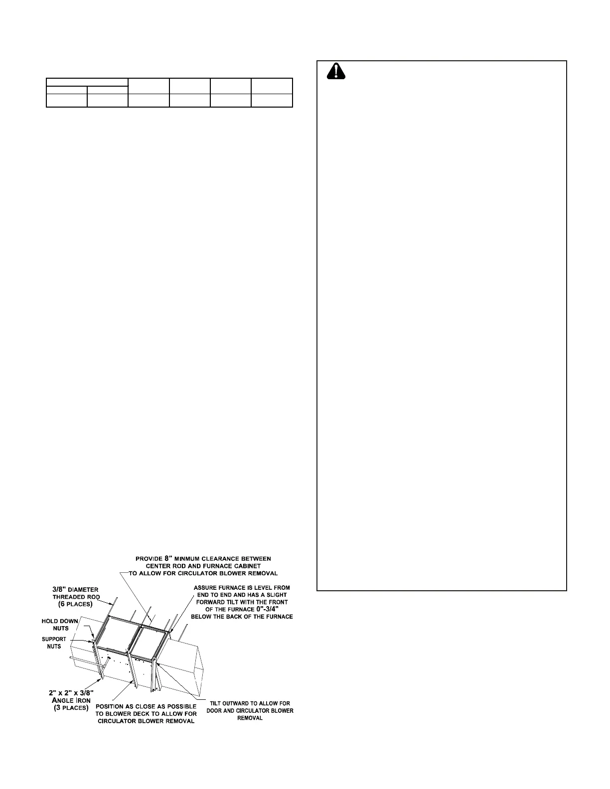
furnACe SuSpenSion
If suspending the furnace from rafters or joist, use 3/8” thread-
ed rod and 2”x2”x3/8” angle iron as shown below. The length
of rod will depend on the application and the clearances
necessary.
Suspended Furnace
Figure 2
exiSting furnACe removAl
WARNING
CARBON MONOXIDE POISONING HAZARD
Failure to follow the steps outlined below for each
appliance connected to the venting system being placed
into operation could result in carbon monoxide poisoning or
death.
The following steps shall be followed for each appliance
connected to the venting system being placed into
operation, while all other appliances connected to the
venting system are not in operation:
1) Seal any unused openings in the venting system.
2) Inspect the venting system for proper size and horizontal
pitch, as required in the National Fuel Gas Code, ANSI
Z223.1/NFPA 54 or the Natural Gas and Propane
Installation Code, CSA B149.1 and these instructions.
Determine that there is no blockage or restriction,
leakage, corrosion and other deficiencies which could
cause an unsafe condition.
3) As far as practical, close all building doors and windows
and all doors between the space in which the
appliance(s) connected to the venting system are located
and other spaces of the building.
4) Close fireplace dampers.
5) Turn on clothes dryers and any appliance not connected
to the venting system. Turn on any exhaust fans, such as
range hoods and bathroom exhausts, so they are
operating at maximum speed. Do not operate a summer
exhaust fan.
6) Follow the lighting instructions. Place the appliance being
inspected into operation. Adjust the thermostat so
appliance is operating continuously.
7) Test for spillage from draft hood equipped appliances at
the draft hood relief opening after 5 minutes of main
burner operation. Use the flame of a match or candle.
8) If improper venting is observed during any of the above
tests, the venting system must be corrected in
accordance with the National Fuel Gas Code, ANSI
Z223.1/NFPA 54 and/or Natural Gas and Propane
Installation Code, CSA B149.1.
9) After it has been determined that each appliance
connected to the venting system properly vents when
tested as outlined above, return doors, windows, exhaust
fans, fireplace dampers and any other gas-fired burning
appliance to their previous conditions of use.
 Loading...