10
When a furnace is installed horizontally with left side down
the front cover pressure switch tube must be re-located to
the lower port of the collector box cover.
1. Remove tube from front cover pressure switch and
collector box cover.
2. Remove rubber plug from bottom collector box port
and install on top collector box port.
3. Locate 24” x 1/4” tube in bag assembly.
4. Install one end on front cover pressure switch.
5. Route tube to lower port on collector box cover and
cut o excess tubing.
In horizontal applications the condensate drain trap is
secured to the furnace side panel, suspending it below the
furnace. A minimum clearance of 5 ½” below the furnace
must be provided for the drain trap. Additionally, the
appropriate downward piping slope must be maintained
from the drain trap to the drain location. Refer to
for further details. If the
drain trap and drain line will be exposed to temperatures
near or below freezing, adequate measures must be taken
to prevent condensate from freezing.
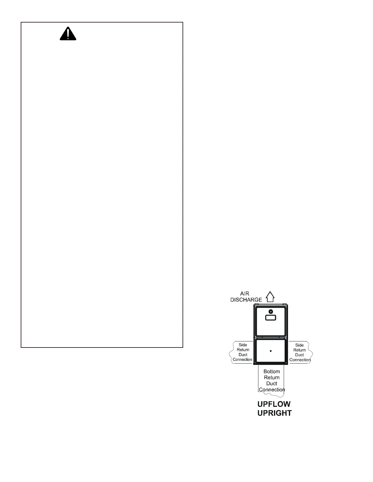
Leveling ensures proper condensate drainage from the
heat exchanger. For proper ue pipe drainage, the
furnace must be level lengthwise from end to end. The
furnace should have a slight tilt from back to front with the
access doors downhill from the back panel approximately
1/2 to 3/4 inches. The slight tilt allows the heat exchanger
condensate, generated in the recuperator coil, to ow
forward to the recuperator coil front cover.
When installing a furnace horizontally, additional
consideration must be given to the following:
If suspending the furnace from rafters or joists, use 3/8”
threaded rod and 2”x2”x1/8” angle iron as shown in the
following diagram. The length of rod will depend on the
application and the clearances necessary.
If the furnace is installed in a crawl space it must be
suspended from the oor joist or supported by a concrete
pad. Never install the furnace on the ground or allow it to
be exposed to water.
 Loading...