37
wiring must conform to all local codes, and have a
minimum temperature rating of 105°C.
• All line voltage wire splices must be made inside the
furnace junction box.
Furnace must have a 115 VAC power supply properly
connected and grounded. Proper polarity must be
maintained for correct operation. In addition to the
following start-up and adjustment items, refer to further
information in section.
Check that all furnace cabinet sealing components are in
place (plugs, grommets, gaskets). NOTE: If the furnace
bottom panel has not been removed for a return duct
connection, all perforations must be sealed with duct
sealant compound or other suitable method to prevent
air leakage. For optimal performance verify that all door
gaskets are properly in place and replace as needed to
prevent air leakage.
The drain trap MUST be primed prior to furnace startup.
To prime, ll both sides of the drain trap with water. This
ensures proper furnace drainage upon startup and
prohibits the possibility of ue gases escaping through the
drain system.
Purge gas lines of air prior to startup. Be sure not purge
lines into an enclosed burner compartment. Follow NFPA
54, National Fuel Gas Code for proper purging methods.
In Canada, follow approved purging methods in CAN/CSA
B149.1-15.
Check for leaks using an approved chloride-free soap and
water solution, an electronic combustible gas detector,
or other approved method. Verify that all required kits
(propane gas, high altitude, etc.) have been appropriately
installed.
1. Close the manual gas shuto valve external to the
furnace.
2. Turn o the electrical power to the furnace.
3. Set the room thermostat to the lowest possible
setting.
4. Remove the burner compartment door.
5. Move the furnace gas valve manual control to the
OFF position.
6. Wait ve minutes then smell for gas. Be sure check
near the oor as some types of gas are heavier than
air.
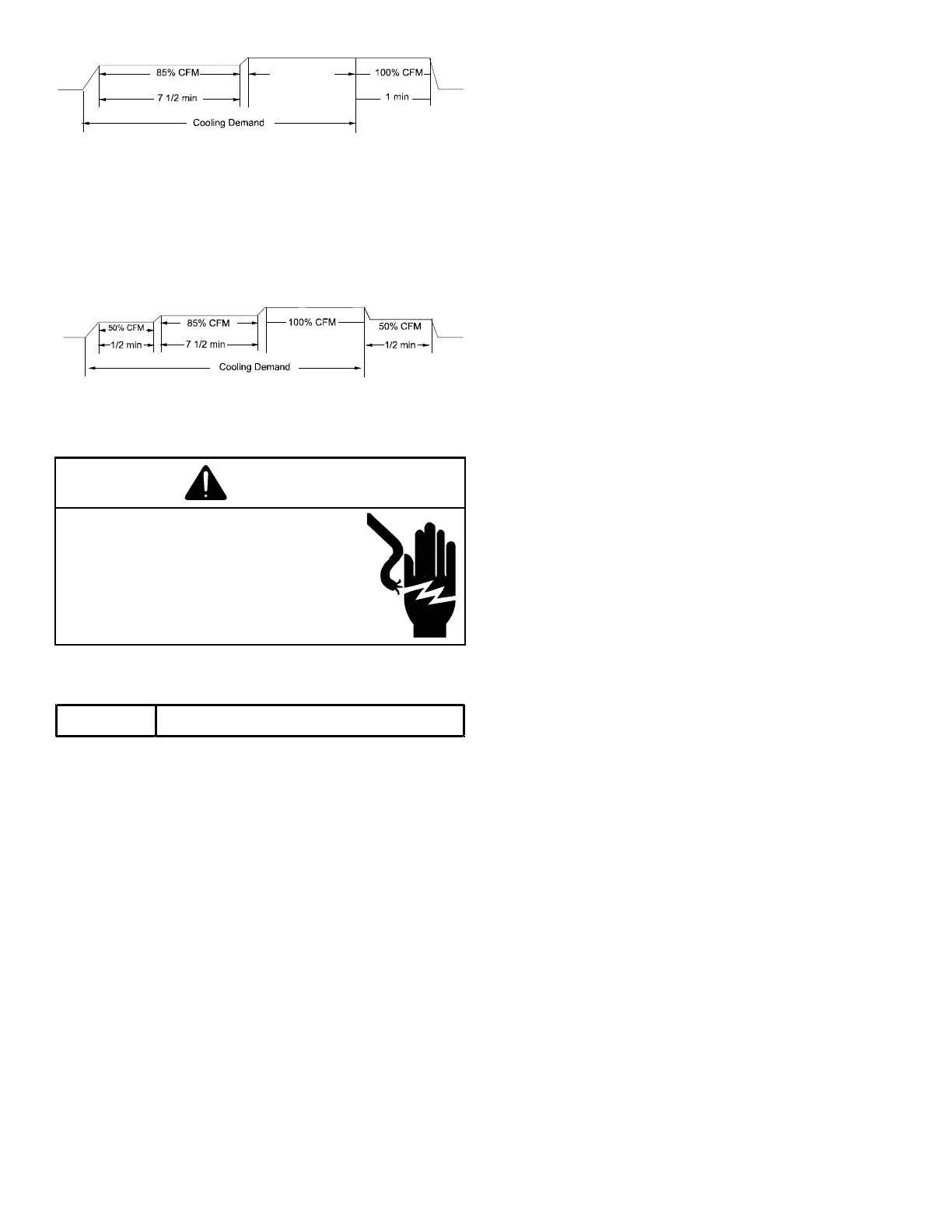
(4) ramps up to 50% of the demand for 1/2
minute, then ramps to 85% of the full cooling demand
airow and operates there for approximately 7 1/2
minutes. The motor then steps up to the full demand
airow. Prole D has a 1/2 minute at 50% airow OFF
delay.
WARNING
The accessory load specications are as follows:
EAC 1.0 AMP maximum at 120 VAC
The furnace integrated control module is equipped with a
line voltage accessory terminal for controlling power to an
optional eld supplied electronic air cleaner or any device
required to operate inparallel with a circulating fan demand.
To connect an electronic air cleaner using the line voltage
EAC terminal:
• Turn OFF power to the furnace before installing any
accessories.
• Follow the air cleaner manufacturers’ instructions
for locating, mounting, grounding, and controlling
accessories. Utilize 1/4” quick connect terminals to
make accessory wiring connections to the furnace
integrated control module.
• Connect the hot terminal utilized for accessory
operation to the EAC terminal and the neutral side
of power to NEUTRAL bus on the integrated furnace
control or the neutral connection in the furnace
junction box.
• All eld wiring must conform to applicable codes.
• If it is necessary for the installer to supply additional
line voltage wiring to the inside of the furnace, the
 Loading...