5
The best protection for the wiring is the lowest rated
fuse or circuit breaker which will supply power to the
unit during normal operation without nuisance trips.
Such a device will provide maximum circuit protection.
DO NOT EXCEED THE MAXIMUM OVERCURRENT
DEVICE SIZE SHOWN ON UNIT DATA PLATE.
All line voltage connections must be made through
weatherproof fittings. All exterior power supply and
ground wiring must be in approved weatherproof con-
duit. Low voltage wiring from the unit control panel to
the thermostat requires coded cable.
Flexible Set-Up For Wiring On The Left Or Right
Side
Even though the electrical box is on the left side of the
unit, both line voltage and low voltage wiring can enter
the unit according to the following (see dimension draw-
ing on the Specification Sheet for knockout locations):
• Line voltage, electrical heater wiring, and low volt-
age on the right side.
• Line voltage and low voltage wiring on the left side
with electrical heater wiring on the right side.
• Line voltage and electrical heater wiring on the right
side with low voltage wiring on the left side.
• Low voltage wiring on the left side and line voltage
and electric heater wiring on the right side.
Using the single-point wiring kit adds further flexibility to
installation wiring.
Unit Voltage
The unit transformer is factory connected for 230V
operation. If the unit is to operate on 208V, reconnect
the transformer primary lead as shown on the unit
wiring diagram.
Thermostat Wiring
When an electric heater is installed, the thermostat
wiring will be made at the heater accessory box.
If no heater is installed, the thermostat wiring will be
made to the low voltage control board.
See the unit wiring diagram for electrical connections.
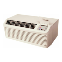
O
R
W
Y
G
O
R
W
Y
G
From
Unit
Figure 5
Typical Thermostat and Unit 24 V Wiring
Hookup
Vl. Circulating Air and Filters
Airflow Conversion
Units can easily be converted from horizontal to vertical
airflow delivery.
Units will ship from the factory ready for horizontal
airflow. If conversion to vertical airflow is necessary,
proceed as follows:
1. Cut insulation around bottom openings and remove
panels from the bottom of the unit, saving the
screws holding the panels in place.
2. From the rear of the unit, remove the four screws
securing the blower assembly in place and loosen
the two screws directly below the duct opening.
(Figure 6)
Remove
Loosen
Figure 6
Duct Removal
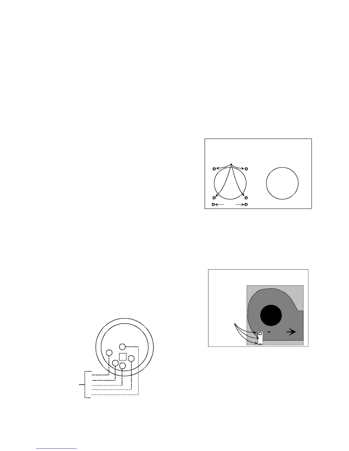
3. Remove the clamp securing the blower assembly to
the bottom of the unit. The clamp and screws may
be discarded. (Figure 7)
Airflow
Remove
Figure 7
Clamp Removal
4. Rotate the blower assembly 90° clockwise, setting
the blower assembly outlet on the bottom of the unit
and secure with two screws removed in step 2.
(Figure 8)
 Loading...