Component Testing Procedures
WARNING
To avoid risk of electrical shock, personal injury, or death, disconnect power to oven and discharge capacitor
before servicing, unless testing requires it.
RS2220001 Rev. 219
Illustration Component Test Results
12
3
5
4
6
AB
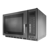
Relay
3
4
AB
Remove all wires from relay.
Measure resistance:
A to B (coil)
3 to 4 (contacts)
With 12 VDC across the coil (A to B)
Measure resistance:
3 to 4 (contacts)
Approximately 120
Ω
Infinite
Ω
0
Ω
J2
J1
J4
J6
White
Red
Yellow
Orang e
J5
J3
1
1
1
1
1
1
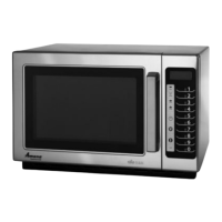
High voltage board
J6 connections
1
−
White
2
−
Open
3
−
Red
4
−
Open
5
−
Yellow
6
−
Orange
Connector Plugged-In
J2
Pin 5 (violet) to ground
J2
Pin 6
J2
Pin7 (blue) to ground
J6
Pin 6 (orange) to Pin 1 (white)
J6
Pin 5 (yellow) to Pin 1 (white)
J6
Pin 1 (white) to Pin 3 (red)
−
27 VDC
Ground
+
18 VDC
230 volts
output to blower and
antenna motors when line voltage is
230 V
208 volts
output to auto transformer
for blower and antenna motors when
line voltage is 208 V
Line voltage
1
1
1
J1
J2
J3
J4
J5
1
1
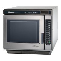
Low voltage board
J3 connector is for
side keypad ribbon.
J4 connector is for
top keypad ribbon.
Connector Plugged-In
J2
Pin 5 (violet) to ground
J2
Pin 6
J2
Pin7 (blue) to ground
J3 connector is for side keypad ribbon.
J4 connector is for top keypad ribbon.
−
27 VDC
Ground
+
18 VDC
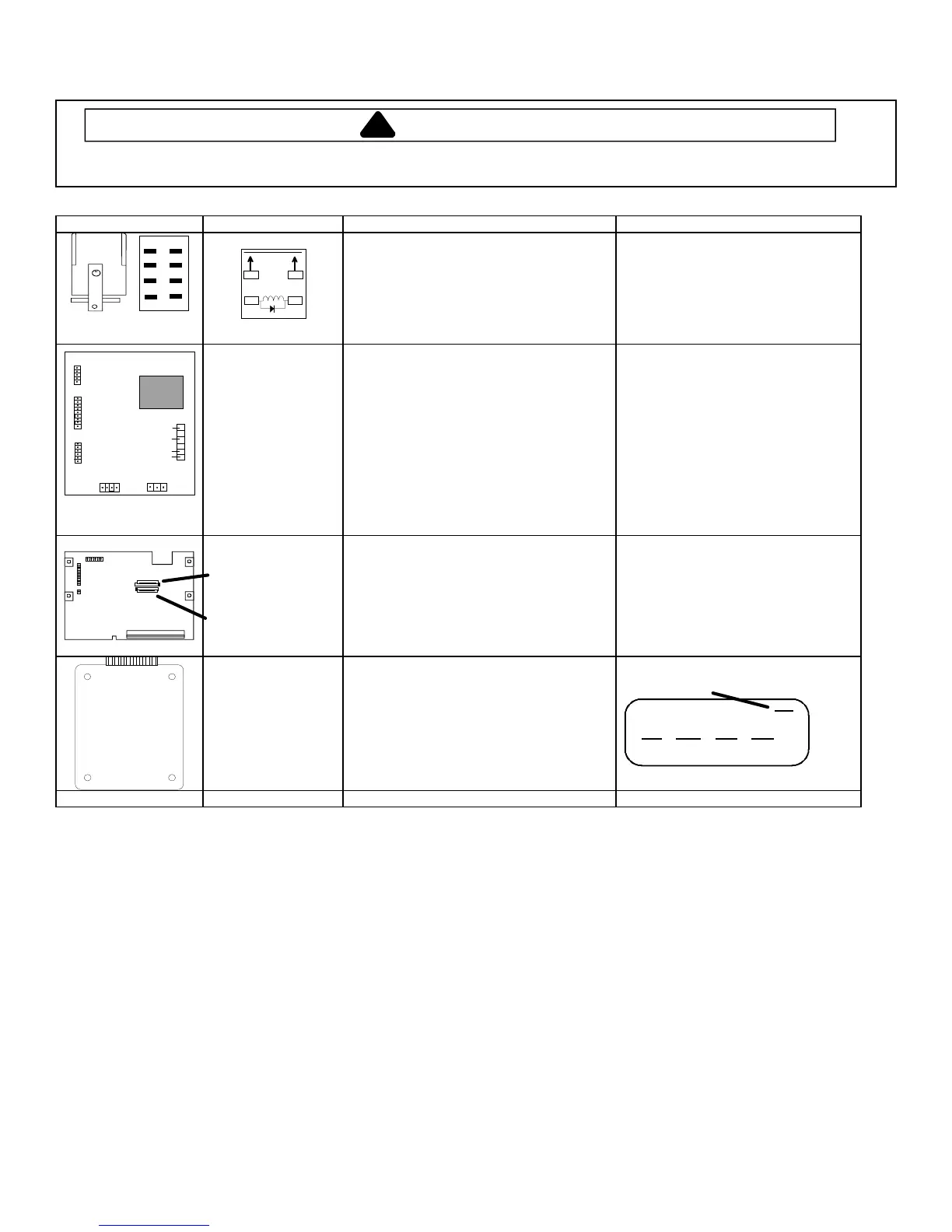
Extended memory
board
MC and DQ only
1) Unplug oven for 1 minute.
2) Close oven door.
3) Plug oven in.
This dash must be lit (top segment of
far right digit).
Wire Harness Test continuity of wires. Indicates continuity
 Loading...