1
Ag. 7
1
Ag. 8
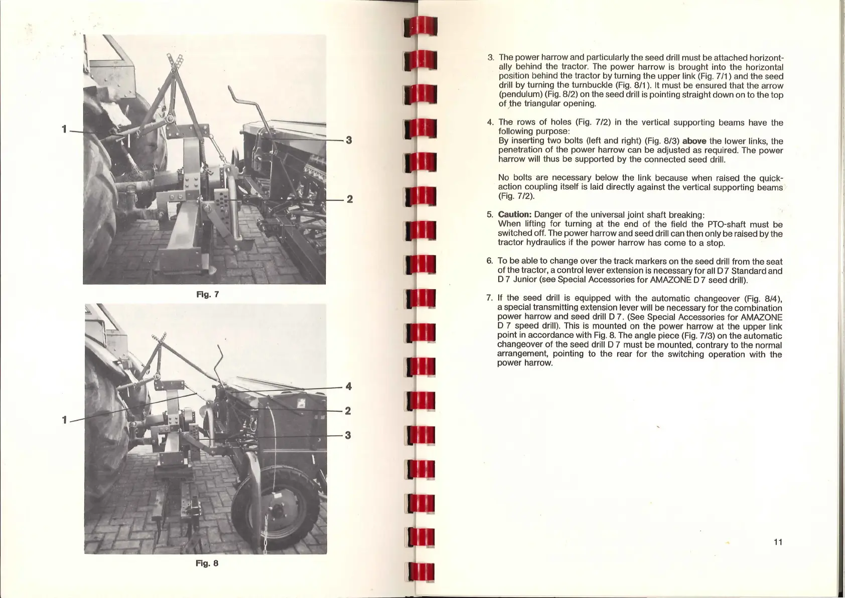
3.
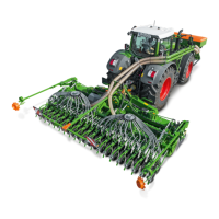
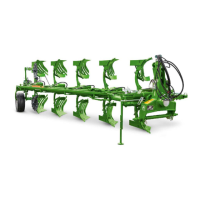
The power harrow and particularly the seed drill must be attached horizont-
ally behind the tractor.
The
power harrow
is
brought into the horizontal
·position behind the tractor by turning the upper link
(Fig.
7 /1) and the seed
drill by turning the turnbuckle
(Fig.
8/1
).
It must be ensured that the arrow
(pendulum)
(Fig.
8/2)
on
the seed drill
is
pointing straight down
on
to the top
of
J
he
triangular opening.
4. The rows of holes
(Fig.
7 /2)
in
the vertical supporting beams have the
following purpose:
By
inserting two bolts (left and right)
(Fig.
8/3) above the lower links, the
penetration of the power harrow can be adjusted
as
required. The power
harrow will thus be supported by the connected seed drill.
No
bolts are necessary below the link because when raised the quick-
action coupling itself
is
laid directly against the vertical supporting beams '
(Fig.
7/2).
5.
Caution: Danger
of
the universal joint shaft breaking:
When lifting for turning at the end
of
the field the PTO-shaft must be
switched off. The power harrow and seed drill can then only be raised by the
tractor hydraulics if the power harrow has come to a stop.
6.
To
be able to change over the track markers
on
the seed drill from the seat
of the tractor, a control lever extension
is
necessary for
all
D 7 Standard and
D 7 Junior (see Special Accessories for AMAZONE D 7 seed drill).
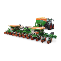
7.
If the seed drill
is
equipped with the automatic changeover
(Fig.
8/4
),
a special transmitting extension lever will be necessary for the combination
power harrow and seed drill D 7.
(See
Special Accessories for AMAZONE
D 7 speed drill). This
is
mounted
on
the power harrow at the upper link
point
in
accordance with
Fig.
8.
The angle piece
(Fig.
7 /3)
on
the automatic
changeover
of
the seed drill D 7 must be mounted, contrary to the normal
arrangement, pointing to the rear for the switching operation with the
power harrow.
11
 Loading...