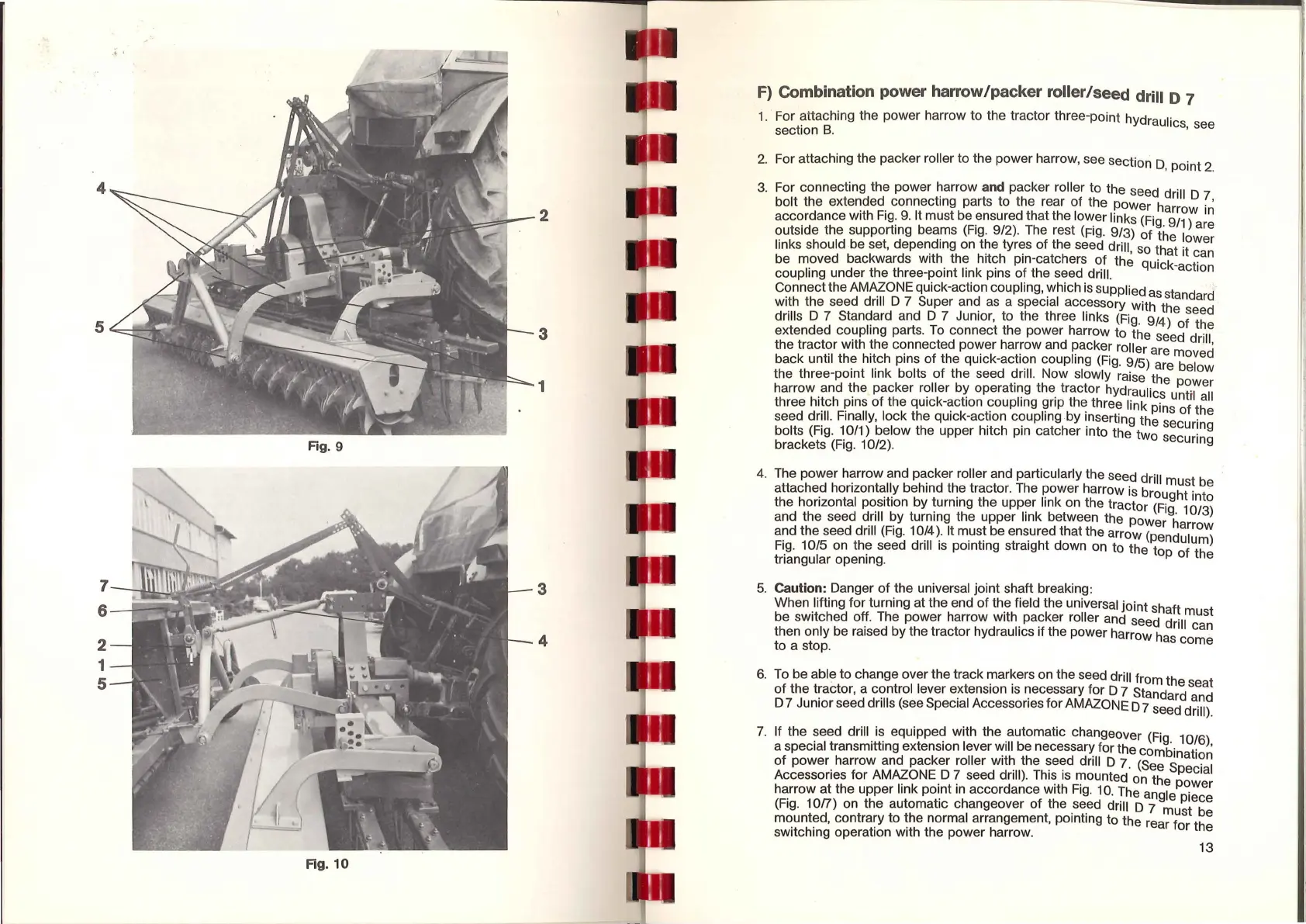
Fig. 9
7
5--1
::::..=:~1=:J~~
....
~~~
2
1
5
Fig. 10
2
3
1
3
4
f)
Combinati
on
power harrow/ packer
ro
ll
er/ seed dr
ill
D
7
1.
· For attaching the power harrow
to
the tractor three-point hydraulics see
section
B.
'
2.
For attaching the packer roller to the power harrow, see section
o,
point
2
_
3.
For connecting the power harrow and packer roller
to
the seed drill
O
7
bolt the extended connecting parts to the rear
of
the power harrow
i~
accordance with
Fig:
9.
It must be ~nsured that the
lo~er
links (Fig. 9
11
) are
outside the
supporting beams
(Fig.
9/2). The rest
(fig.
9/3)
of
the lower
links should be set, depending on the tyres
of
the seed drill, so that it can
be moved backwards
with_
th~ hit~h pin-catchers
~f
the quick-action
coupling under the
three-point link pins
of
the seed drill.
Connect the AMAZONE quick-action coupling,
~hich
is
supplied
as
standard
with the seed drill D 7 Super
an~
as
a special acc_essory with the seed
drills D
7 Standard and D 7 Junior, to the three links (Fig. 9/4)
of
the
extended coupling parts.
To connect the power harrow
to
the seed drill
the tractor with the connected power harrow and
~acker roller are moved
back until the hitch pins
of
the quick-acti?n coupling
(Fig.
9/5) are below
the three-point link bolts
of
the seed ?rill. Now slowly raise the power
harrow and the packer
r<;>ller
b~ operat1~g
the_
tractor hydraulics untrl
all
three hitch pins
of
the
qu1ck-~ct1on
?oupling ~rip th~ three link pins
of
the
seed drill. Finally, lock the
qu1ck-ac~1on
c?upling
by
1_nserting
the securing
bolts (Fig.
10/1) below the upper hitch
pm
catcher into the two securing
brackets (Fig. 10/2).
4.
The
power
harrow and packer roller and particularly the seed drill must be
attached horizontally behind the tractor. The
power harrow
is
brought into
the horizontal position by turning the upper
link on the tractor (Fig.
1013
)
and the seed drill
by
turning the upper link between the power harrow
and the seed drill (Fig.
10(4
~-
It
m_us~
be en~ured that the arrow (pendulum)
Fig
. 10/5 on the seed drill
1s
pointing straight down on to the top
of
the
triangular opening.
5.
Ca
ution: Danger
of
the universal joint shaft breaking:
When lifting for turning at the end
of
th_e
field the universal
joint
shaft must
be switched off. The power harrow
with. pa?ker roller and seed drill can
then only be raised
by
the tractor hydraulics
1f
the power harrow has come
to a stop.
6.
To
be able
to
change over the track markers on the seed drill from the seat
of
the tractor, a c?ntrol lever e~tension
is
~ecessary for D 7 Standard and
D 7 Junior seed
drills (see Special Accessories for AMAZONE D 7 seed drill).
7.
If the seed drill is equipped with the automatic changeover (Fig.
1016
)
a special transmitting extension lever will be necessary for the combinatio~
of
power
harrow and packer roller wit~ the ~e~d drill D 7. (See Special
Accessories for AMAZONE. D
? seed drill).
Thi~
1s
'"!lounted on the power
harrow at the upper link
point
in
accordance with
Fig.
10.
The angle piece
(Fig. 10/7) on the automatic changeover of the
_
se_ed
drill D 7 must be
mounted, contrary
to
the normal arrangement, pointing to the rear
for
the
switching operation with the power harrow.
13
 Loading...