5
1. Unit does not spray a. Vacuum Pump not switched on
b. Vacuum line not airtight
c. Constricted Vacuum Supply Pipe (E)
d. Chemical Container is empty
e. Intake Filter (D) blocked
f. Pressure Line (F) blocked
g. Spray Nozzle ATS/415 (or AJS/2415)
blocked
h. Unsuitable chemical being used
i. Pump ATS/426 faulty
j. Directional Valve ATS/425 faulty
k. Dump Valve AJS/2006 faulty
a. Air in pressure Line (F)
b. Control Valve ATS/405 dirty or
damaged
a. Loose Connector Nut
b.
Defective Pump or Relief valve
Relief Valve faulty
Relief Valve or Pump faulty
a. Switch on Vacuum Pump
b. Check that Vacuum is reaching Power Unit.
Check Vacuum Pipe adaptor is correctly
installed
c. Check for kinks and overtightened Cable Ties
d. Fill Container
e. Clean Filter
f. Clear blockage, check for kinks, constrictions
and tight Cable Ties
g. Disassemble, clean Nozzle (see Figs. 11
& 14)
h. Change to recognised Teat Disinfectant
i. Check Pump and repair or replace
j. Check Valve and repair or replace
k. Check Valve and clean, repair or replace
a. Vent as described under “Initial start up”
b. Clean or replace Control Valve
a. Locate leak and tighten Nut
b.
Check Units and r
epair or r
eplace
Repair or replace
Immediately disconnect Vacuum line & plug it.
Repair or replace defective parts.
2. Nozzle (Figs.12 & 14)
does not shut off cleanly
or Leaks
3.
Chemical r
unning out of
Power Unit
4.
Unit pr
essurised when
Vacuum switched off
5. Chemical leaks into
Vacuum line
F
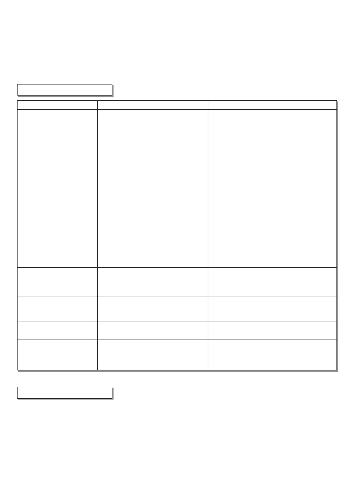
AULT
CAUSE
REMEDY
11. TROUBLE SHOOTING
Power Source Vacuum 12-15”Hg (40-50 kPa) Maximum No. of guns operated
simultaneously 2
Chemical Consumption
6-14 ml/Sec per gun
Maximum No. of Guns per Power Unit
20
Air Consumption 50 l/min (1.8cfm Atmospheric Air @ 50 kPa) Maximum length of Pressure Line 25 m (80 ft)
Spray Pressure 40psi (3bar) @ 50 kPa (15”Hg)
12. TECHNICAL DATA
ATS/456 (FIG. 7) is possible, but it is difficult without the use of
specially-adapted tools to hold the body and to unscrew the
pump heads.
When replacing the Pump, make sure that the arrows on the
Pump Heads point towards the top of the Power Unit.
Occasionally, debris may enter the Non Return Valves ATS/445
and ATS/446 (FIG. 7). These can be unscrewed using suitable
pliers. Wash out and blow through. These components can be
replaced if damaged.
D
D
U
U
M
M
P
P
/
/
R
R
E
E
L
L
I
I
E
E
F
F
V
V
A
A
L
L
V
V
E
E
A
A
j
j
S
S
/
/
2
2
0
0
0
0
6
6
Valve is located at bottom
right of Power Unit AJS/2006 (FIG. 2). To replace Diaphragm
ATS/435 (FIG. 10), unscrew top with moulded lugs, this will
expose Diaphragm for replacement.
To replace or remove complete Relief Valve, first remove
whole unit from wall and undo the one Philips Screw
securing the Relief Valve to the base. Unscrew the 3 nuts on
the Relief Valve, warm the tube ends and pull off gently
noting their positions.
 Loading...