13
Model
AR/ARE13
AR/ARE22 AR/ARE35 AR/ARE40 AR/ARE45 AR/ARE50
A Above reflector 150 150 150 150 150 150
B Above burner fan assembly flued 500 500 500 500 500 500
C&E Beneath tubes 1250 1250 1500 2100 2100 2100
D To the sides 600 600 600 600 600 600
B From fan outlet unflued 1200 1200 1200 1200 1200 1200
Clearance distances
All dimensions are in millimetres.
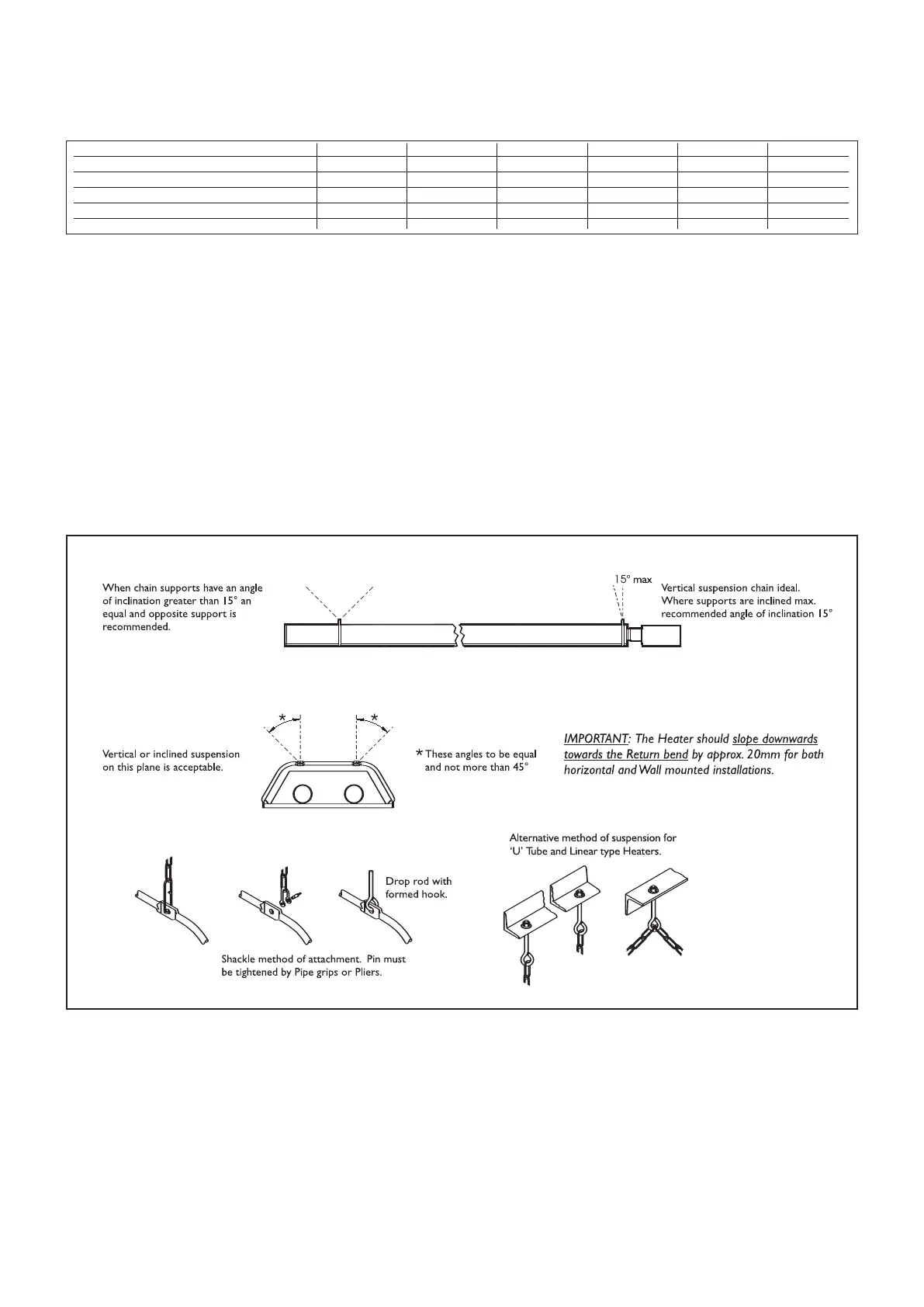
We recommend that at this stage the
tube assembly is raised into position and
suspended by its two end brackets only
from previously fixed chains, of 4mm
gauge galvanised welded link construction
or fixed to two wall mounting brackets
which must incorporate a short section
of hanging chain to allow movement due
to thermal expansion.
Alternatively 10mm diameter mild steel
drop rods can be used. Wall mounting
brackets must support the heater at an
angle of inclination of between 35
º
and 55
º
and are available from the manufacturer.
The angle is varied by adjusting the drop
rods or chain on each bracket. These bracket
positions are critical and when suspended,
must have the same orientation ie. all the
same angle.
UT only
Note If the heater is to be wall mounted the
return bend must be on the left hand side
when viewed facing the wall, with the
burner fitted to the tube nearest the floor.
Figure 12 Methods of heater suspension
 Loading...