Introduction
11
MBRELL
-
-
Precision Induction Heating
1
2
3
6
4 5
8
7
Y
X
1
1
.
.
4
4
A
A
s
s
s
s
e
e
m
m
b
b
l
l
y
y
Take these factors into consideration as you determine where to install your system:
availability of water and drain
availability of 3 AC power
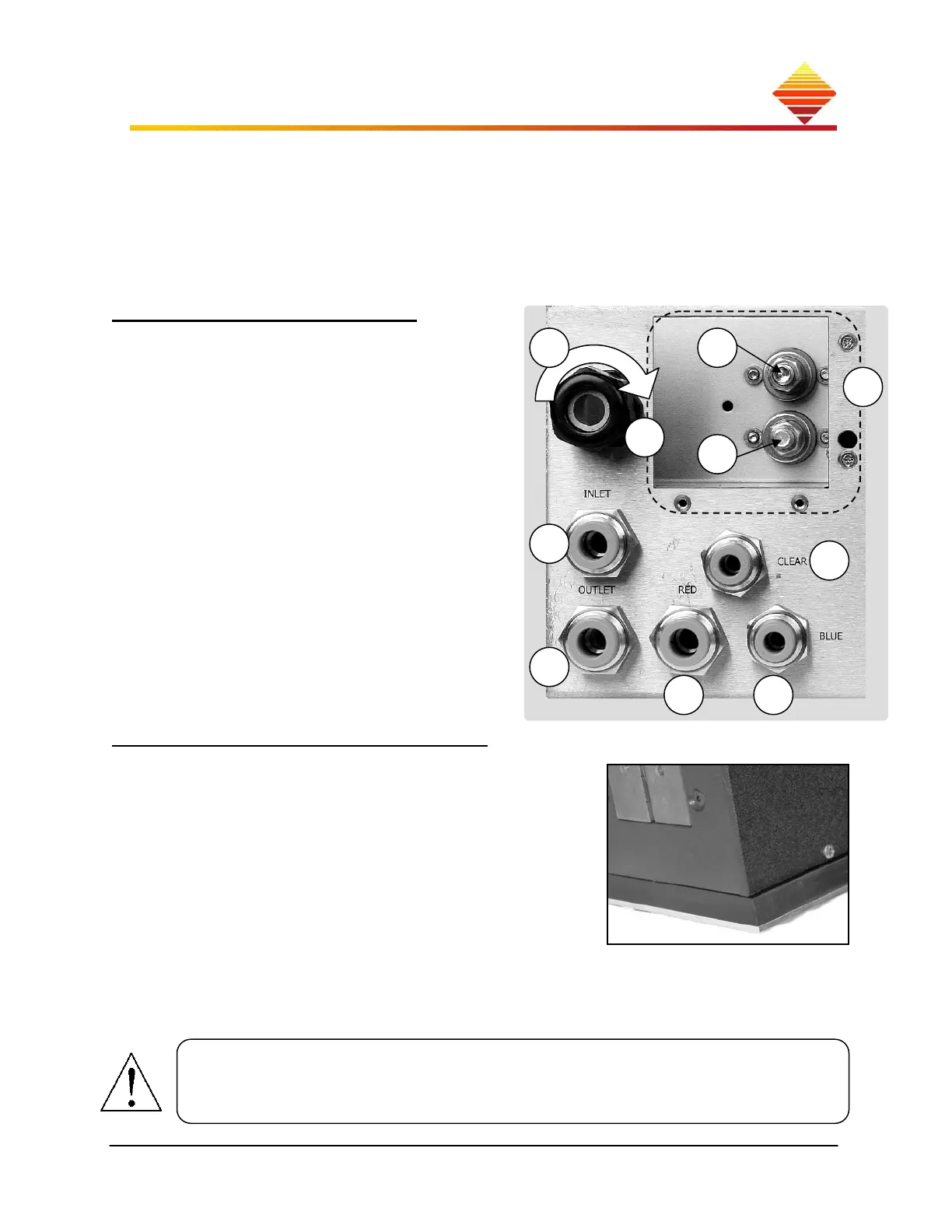
Attach work head & water
remove RF cover (dotted)
insert ring-terminated cable pair from
workhead; secure two ring-terminated
connection at posts as labeled
tighten strain relief nut
insert RED tube from work head
insert BLU tube from work head
insert CLEAR tube from work head
insert tubing for water outlet fully into
bottom port
insert tubing for water inlet fully into
top port
replace RF cover
…to remove tubing
push in on retaining rings, pull out tubes
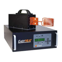
Work head mounting base options
Your work head has been fitted with a two-part
mounting insert, which elevates and insulates the bottom
of the unit from your metal tabletop or mounting fixture,
reducing the amount of secondary heating you might
experience under certain sustained operating conditions.
Secured with four M6 nylon screws, this base can be
utilized or omitted in your mounting scheme. To mount:
remove nylon screws. Replace with four M6 stainless
steel screws long enough to pass through your
mounting surface and into the work head mounting base.
To prevent mounting screws from accidental contact with electrical componentry, use
screws which only thread into the mounting base up to 12.7 mm (0.5 in.).
Longer screws will damage equipment and pose an electrical hazard.