EN
11
- Luer channel Can be used only for topical anaesthesia. PU (Polyurethane)
9 On/off button Turns the Ambu® aScope™ on and off PET (Poly Ethylene Phthalate)
10 Bending control lever Moves the distal tip up or down MABS (Methyl Acrylonitrile
Butadiene Styrene)
- Protection pipe Protects the insertion cord during PP (Polypropylene)
transport and storage
- Packaging Sterile barrier Cardboard, tyvek
Table 4 – Functions and materials
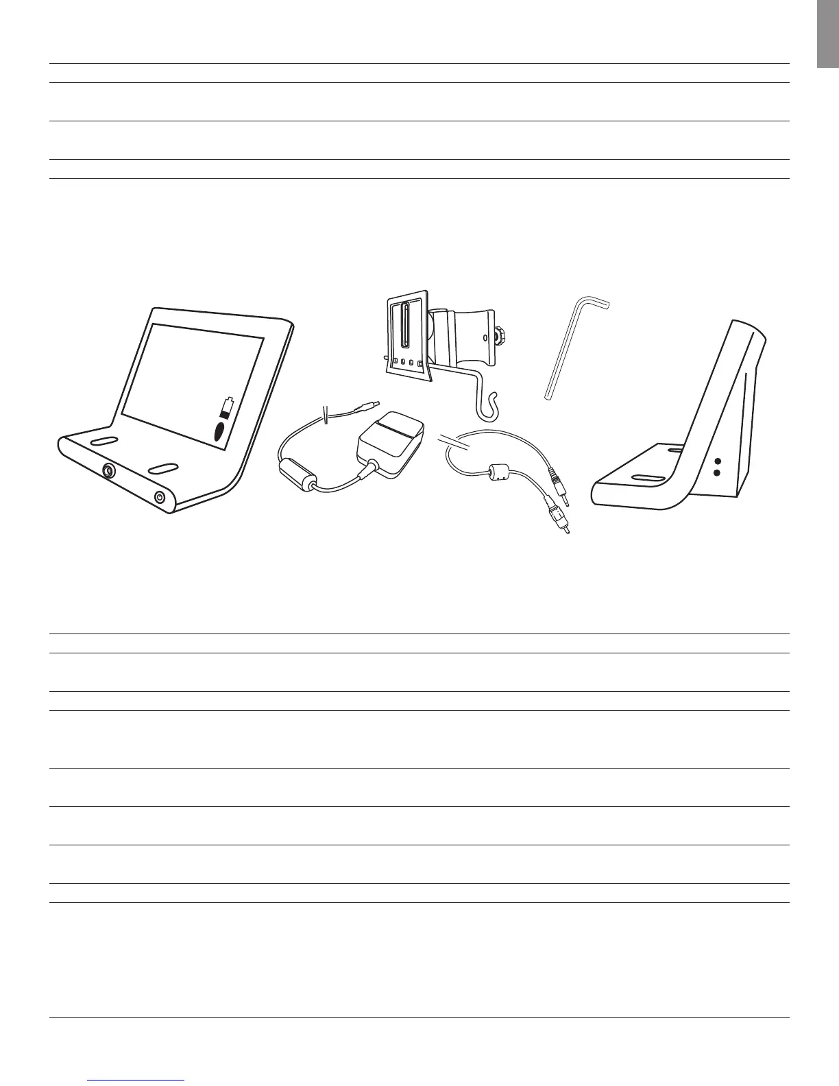
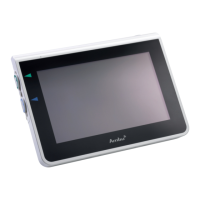
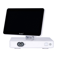
8.2 Ambu® aScope™ Monitor
The monitor displays the video image from the Ambu® aScope™. On startup, it powers the Ambu® aScope™, configures it and checks information from
the Ambu® aScope™ to ensure the Ambu® aScope™ usage is acceptable.
2
7
8
6
5
4
3
12
13
11
9
10
1
Figure 2 - The Ambu® aScope™ Monitor
Number Part Function Material
1 Monitor frame - PC (Polycarbonate) /
ABS (Acrylonitrile Butadiene)
2 Monitor screen Shows the picture from the camera Glass
3 Bracket Secures the monitor to e.g. an IV pole POM -GF25 (Polyoxymethylene
with 25% glass filler) + aluminium
4 Power supply Powers the system PC (Polycarbonate)
5 On/off button Push button for power ON before PC (Polycarbonate)
intubation and power OFF after
intubation.
6 Connection for Power supply and data connection PC (Polycarbonate)
for the Ambu® aScope™ /ABS (Acrylonitrile Butadiene)
7 Brightness This button controls and Silicone
adjusts the brightness.
8 Contrast This button controls and Silicone
adjusts the contrast.
9 Power Power inlet for charging the monitor -
10 Video out The monitor provides a buffered video -
output of the video input from the
Ambu® aScope™. This output is
electrically isolated from the medical
device by the monitor. The signal is a
composite video NTSC signal