EN
10
Plugs
Between the power supply and Ø3.4mm DC jack connector
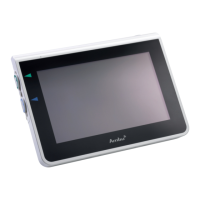
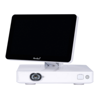
Ambu® aScope™ Monitor
4 interchangeable types 1) Class II model NEMA 1-15P AC power plug with 2 prongs
2) Australian configuration: SAA 2 pins, class II
3) UK configuration: UK 2 pins, class II
4) European configuration: Europlug 2 pins, class II
Table 3 - Specification for the Ambu® aScope™ power supply
8. Ambu® aScope™ functions
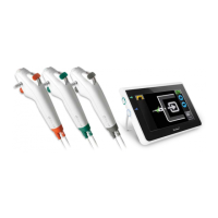
The Ambu® aScope™ system consists of the Ambu® aScope™ and Ambu® aScope™ Monitor. To avoid a possible risk of cross-contamination the
Ambu® aScope™ is a sterile single patient use device.
The Ambu® aScope™ system will prevent reuse of the Ambu® aScope™. The Ambu® aScope™ can be used/switched on for a total of 30 minutes within an
8 hour period from first switching on. When the 30 minute or 8 hour period is exceeded the power to the Ambu® aScope™ system is switched off. When
the Ambu® aScope™ is connected to the Ambu® aScope™ Monitor, do not disconnect the Ambu® aScope™ from the Ambu® aScope™ Monitor within the
first two minutes.
The time remaining for the Ambu® aScope™ will be shown as symbols on the Ambu® aScope™ Monitor at all times when powered on and connected.
See section 8.2.2 for explanation of indicators. The Ambu® aScope™ Monitor is reusable.
If the Ambu® aScope™ Monitor battery icon on the screen changes from green (fully charged battery), via orange (half battery capacity) to red (low bat-
tery capacity) within 30 minutes, it is recommended that the Ambu® aScope™ Monitor is replaced.
The Ambu® aScope™ Monitor can be used for at least 150 intubations if it is stored, used and cleaned as described in this instruction for use.
8.1 Ambu® aScope™
The optical section of the Ambu® aScope™ consists of a camera in a flexible and sealed distal tip. Like all optical systems these parts are very delicate.
Therefore careful handling of the Ambu® aScope™ is recommended.
When turning the Ambu® aScope™ off in between sessions – do not unplug. Simply press the on/off button.
1
2
3
4
5
6
7
8
9
10
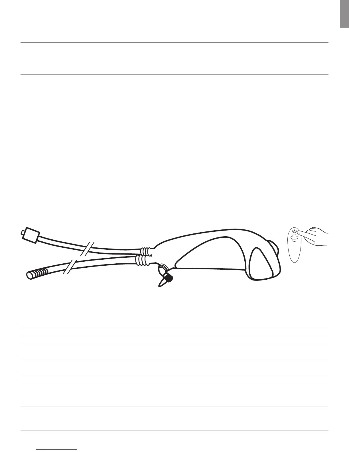
Figure 1 - The Ambu® aScope™
Number Part Function Material
1 Distal tip Camera Epoxy
2 Bending section Manoeuvrable part PU (Polyurethane)
3 Insertion cord Flexible airway insertion cord PU (Polyurethane)
4 Connector on Connects to Ambu® PE (Poly Ethylene) +
Ambu® aScope™ cable aScope™ Monitor PVC (Polyvinyl Chloride)
5 Ambu® aScope™ cable Transmits the picture PVC (Polyvinyl Chloride)
signal to the Ambu®aScope™ Monitor.
6 ET-tube connection Fixes the ET-tube during procedures SEBS (Styrene Ethylene Butadiene)
7 Handle Suitable for both right and MABS (Methyl Acrylonitrile
left handed use Butadiene Styrene) +
SEBS (Styrene Ethylene Butadiene)
8 Luer channel The Luer entry fits a Luer SB (Styrene Butadiene)
entry connector and can be moved
from side to side.