SMD17E2 SPECIFICATIONS
SMD17E2 User Manual
ADVANCED MICRO CONTROLS INC.
20
Status LED’s (continued)
Network Status (NS) LED
The Network Status LED is a bi-color red/green LED. The state of the LED depends on the protocol the
SMD17E2 is configured to for.
Table R1.4 Network Status LED States
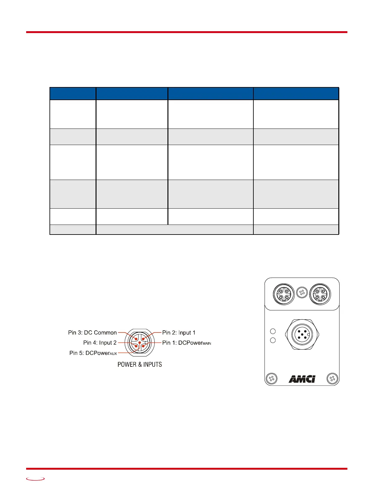
SMD17E2 Connectors
Input Connector
As shown in figure R1.4, the Input Connector is located on the back of the
unit near its center. All digital input and power supply connections are
made at this connector. The connector is a standard five pin A-coded M12
connector that is rated to IP67 when the mate is properly attached. Figure
R1.5 shows the pinout of the connector when viewed from the back of the
SMD17E2.
Digital inputs are single ended and referenced to the DC Common pin.
(Sinking inputs.)
There are two power pins. DCPower
MAIN
powers both the control electron-
ics and the motor. DCPower
AUX
powers only the control electronics. Using
the DCPower
AUX
pin is optional. If your application requires you to cut
power to your motor under some conditions, using the DCPower
AUX
pin
allows you to cut power to your motor without losing your network con
-
nection.
LED State EtherNet/IP Definition Modbus TCP Definition PROFINET Definition
Off No Power
No power or no TCP con-
nections
No power, duplicate IP
address on the network, or
no connection to IO Con
-
troller.
Alternating
Red/Green
Power up Self-Test Power up Self-Test Power up Self-Test
Flashing
Green
Ethernet connection,
but no CIP connec
-
tions
Indicates number of con-
nections with 2 second
delay between group. The
SMD17E2 supports up to 3
concurrent connections.
On-line, Stop state. A con-
nection with the IO Con-
troller is established and it
is in its STOP state.
Steady Green
Valid Ethernet net-
work and CIP con-
nections
Should not occur. LED
should always flash when
network is connected.
On-line, Run state. A con-
nection with the IO Con-
troller is established and it
is in its RUN state.
Flashing Red
Network Connection
Timeout
Not implemented in
Modbus TCP.
Not Implimented
Steady Red Duplicate IP address on network. Not Implimented.
Figure R1.4 SMD17E2
Connector Locations
POWER & INPUTS
Power: 24 to 48 Vdc
Figure R1.5 M12 Input Connector