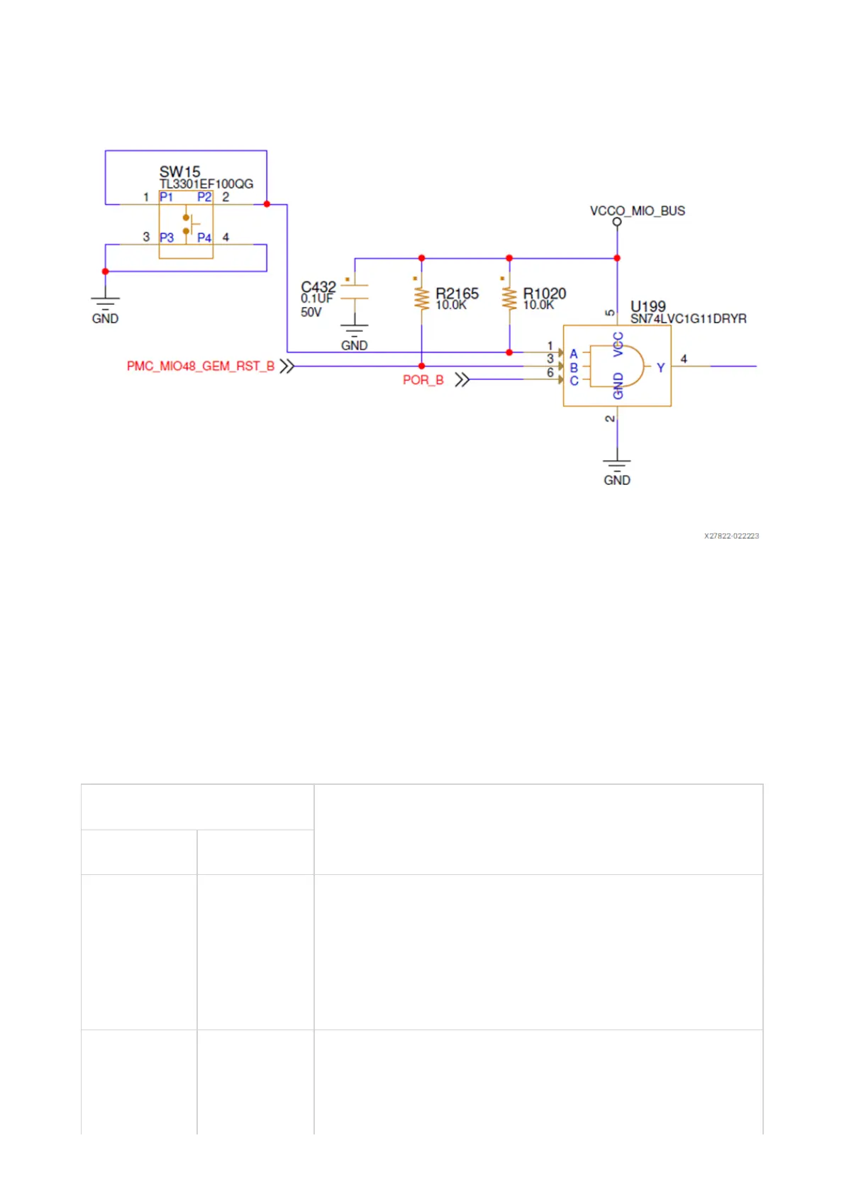
Figure: Ethernet PHY Reset Circuit
Ethernet PHY LED Interface
[Figure 1, callout 19]
The ADIN1300 PHY (GEM0 U198) controls two LEDs in the J307 two port connector
bezel. The PHY signal LED0 drives the green LED, and LED1 drives the yellow LED.
The LED functional description is listed in the following table.
Table: Ethernet PHY LED Functional Description
ADIN1300 PHY Pin Description
Name Number
LED_1 26 By default, this pin indicates that 100BASE-T link is
established. Additional functionality is configurable
using LEDCR1[7:4] register bits. The LINK_ST pin is
a general-purpose output used to indicate to the
MAC whether a valid link has been established.
LED_0 21 By default, this pin indicates that link is established.
Additional functionality is configurable using
LEDCR1[3:0] register bits.