J16. Connecting an ATX 6-pin connector into J16 damages the VEK280 board and
voids the board warranty.
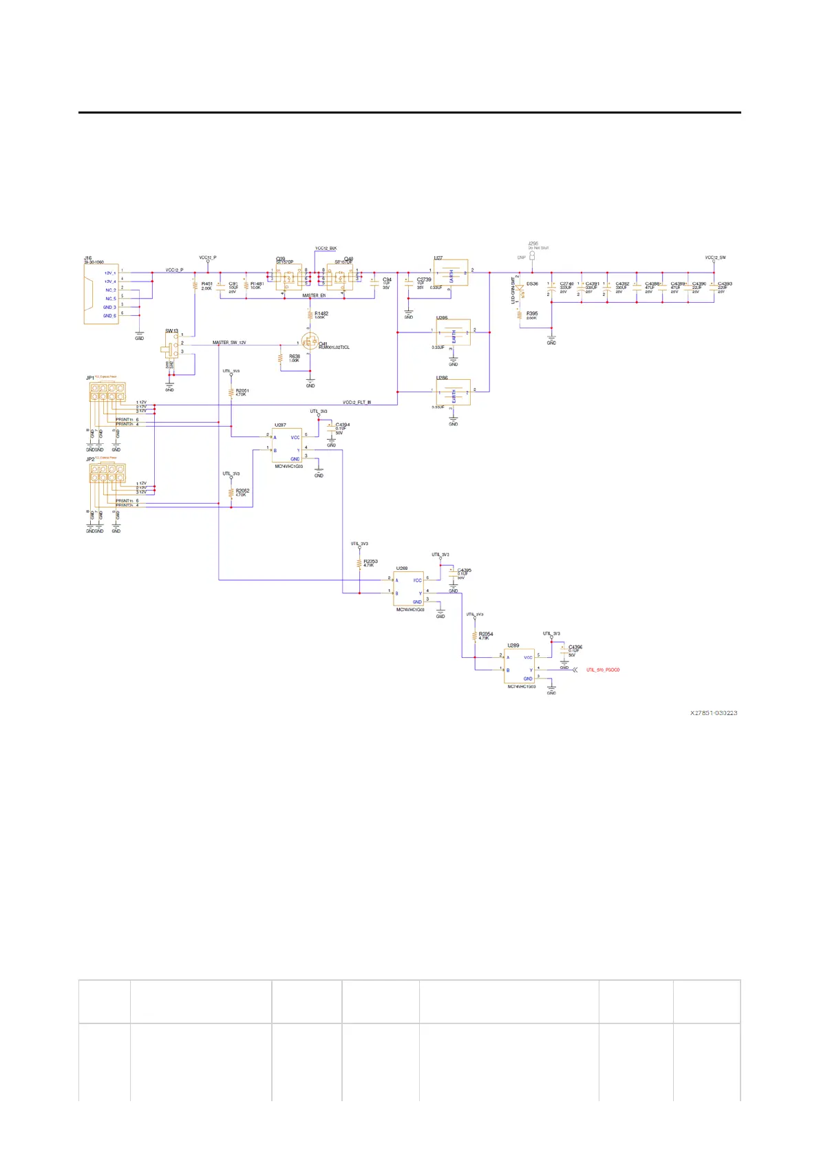
The following figure shows the power connector J16, power switch SW13, and LED
indicator DS36.
Figure: Power Input
Board Power System
[Figure 1, callout 21]
The VEK280 evaluation board uses power management ICs (PMIC) and power
regulators from Infineon Integrated Circuits to supply the core and auxiliary
voltages listed in the following tables. The detailed device connections for the
feature described in this section are documented in the VEK280 board schematic.
Table: Power System - PMBus Regulators and INA226 Map
Rail Rail Name Nominal Voltage (V)Max Current (A)Device PMBUS AddrINA226 Addr
1 VCCINT 0.80 150 U152 L1, U154,
U155, U157, U159,
0x46 0x40
BUS1