2.2.3
2.2.4
2.2.5
INSTALLATION
AND
OPtHA
IIUN
MANUAL,
MUUt:L
f\1\-,ov
OPS
1
NAV
SWITCHINO
&
ANNUNCIATOR
PANEL
ADDITIONAL
ANNUNCIATIONS
Depending
upon
the
installation
and
approving
agency,
you
may
be
required
to
provide
addition
al
NA
V Source Select external
annunciators
near
the
HSI 1 COl. Spare relay
contacts
on
the
AK-950
connector
may
be used
for
this
purpose.
ADDITIONAL
RELA
Y~
The
AK-950
contains
24
relay pales. Some
installations
may
require
more
than
24
pales due
to
data lines, superflags, etc.
If
this
should
occur,
you
may
use one spare relay pole
to
switch
additional relays.
ln
cases
where
it
may
be
more
desirable
to
have ali
the
relay
switching
done
at a
remote
location,
(i.e.:
remote
mounted
equipment).
one relay pole on
the
AK-950
may
be used
for
switching
this
bank
of
relays. Please
note
that
the
maximum
relay
contact
rating
for
the
AK-950
is 2
amps
DC.
ROUTING
OF
GABLES
Care
must
be
taken
not
to
bundle
the
AK-950
logic and
low
level signal lines
with
any
high
energy
sources. Examples
of
these
sources
include
400
Hz AC,
Comm.
DME, HF and
transponder
transmitter
coax.
Always
use shielded
wire
when
shawn
on
the
installation
print.
Avoid
sharp
bends
in cabling
and
routing
near
aircraft
control
cables.
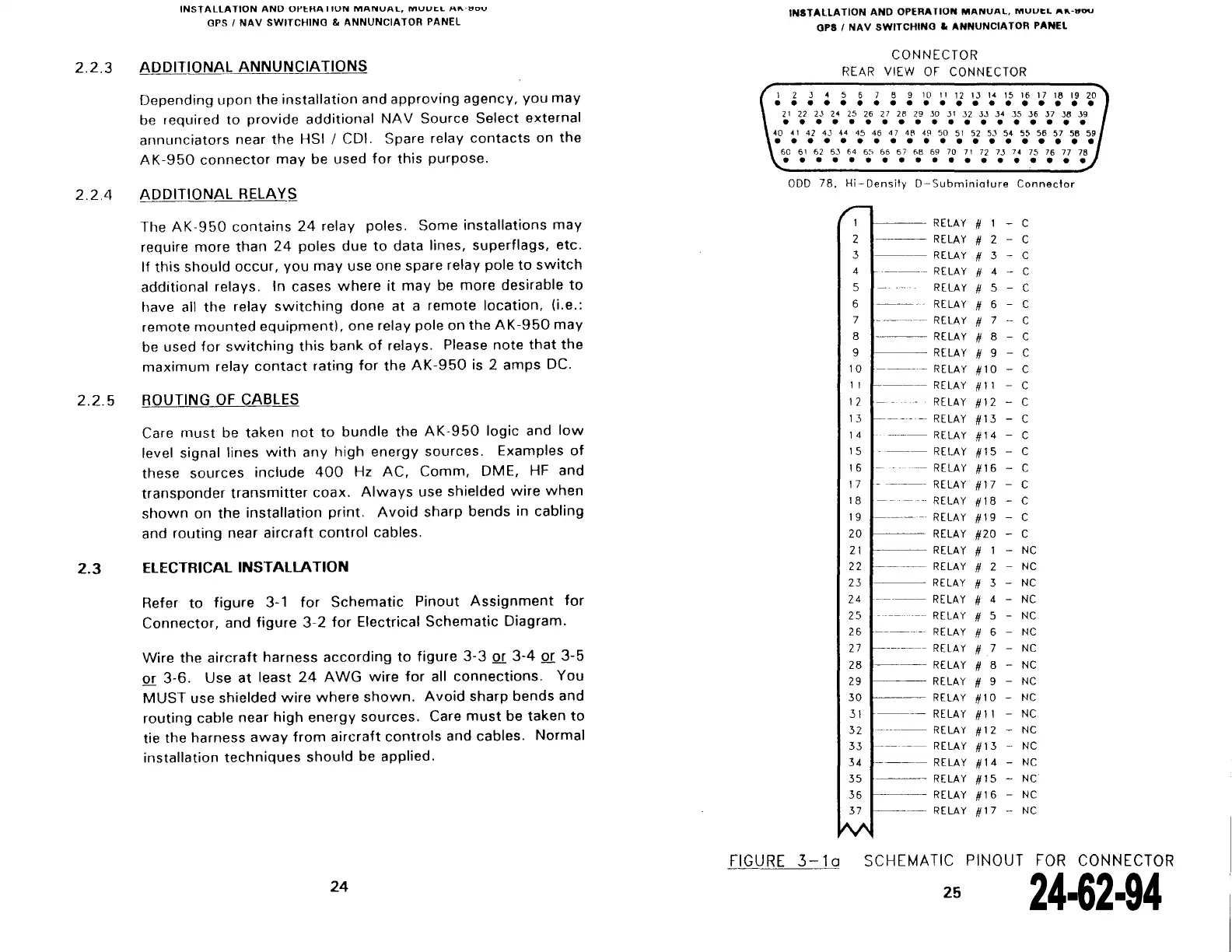
2.3
ElECTRICAliNSTAllATION
Refer
to
figure
3-1
for
Schematic
Pinout
Assignment
for
Connector,
and
figure
3-2
for
Electrical
Schematic
Diagram.
Wire
the
aircraft
harness
according
to
figure
3-3
or
3-4
or
3-5
or
3-6.
Use
at
least
24
AWG
wire
for
ali
connections.
You
MUST
use shielded
wire
where
shawn.
Avoid
sharp bends and
routing
cable near
high
energy
sources. Care
must
be
taken
to
tie the harness
away
from
aircraft
contrais
and cables. Normal
installation
techniques
should
be applied.
24
INSTALLATION
AND
OPERATION
MANUAL,
MUUI:L
,.,.
• .,ou
OPS
1
NAV
SWITCHINO
a.
ANNUNCIATOR
PANEL
CONNECTOR
REAR
VIEW
OF
CONNECTOR
1 2 J 4 5 6 7 8 9 10
Il
12
IJ
14 15 16
• • • • • • • • • • • • • • • • • • • •
21
22
23
24 25 26
27
28
29
30
31
J2
3J
J4
JS
36
J7
J8 J9
• • • • • • • • • • • • • • • • • • •
40
41
42
43
44
45 46
47
48
4~
50
51
52
53 54 55 56 57
58
59
• • • • • • • • • • • • • • • • • • • •
50
51
62
6J
64
65 66 67 68
69
70
71
72
7J
74
75
76
77
78
• • • • • • • • • • • • • • • • • • •
ODD
78, Hi-Density
D-Subminiature
Conneclor
,-
1
RE
LAY
#
1
-
c
2
~--
RELAY
#
2
-
c
3
----
RELAY
#
3
- c
4
·---
RELAY
#
4 -
c
5
RE
LAY
#
5 c
6
RE
LAY
#
6
c
7
--------
RELAY
#
7
-
c
8
--
---
RELAY
#
8
-
c
9
RE
LAY
#
9
-
c
10
--
--
RELAY
#10
- c
11
1-----
RELAY
#
11
-
c
12
RELAY
#12
c
13
1------
--
RELAY
#13
-
c
1 4
-----
RELAY
#14
-
c
15
----
RELAY
#15
-
c
1 6
-
-
RELAY
#16
c
17
-
----
RELAY
#17
-
c
18
---
-----
RE
LAY
#18
c
19
------
RE
LAY
#19
-
c
20
RELAY
#20
-
c
21
f-----
RELAY
#
-
NC
22
--~-
RELAY
#
2
-
NC
23
RE
LAY
#
3
-
NC
24
--·
--
RELAY
#
4
-
NC
25
----
--
RELAY
#
5
-
NC
26
-------
RE
LAY
#
6
-
NC
27
---------
RELAY
#
7
-
NC
28
---~
RELAY
#
8
-
NC
29
RE
LAY
#
9
NC
30
f-----
RELAY
#10
-
NC
31
----
RE
LAY
#11
-
NC
32
--------
RELAY
#12
-
NC
33
-----
RELAY
#13
-
NC
34
----
RELAY
#14
-
NC
35
-----
RELAY
#15
-
NC
36
1-----
RELAY
#16
-
NC
37
------
RE
LAY
#17
-
NC
~
FIGURE
3-1
a
SCHEMATIC PINOUT
FOR
CONNECTOR
25
The document reference is online, please check the correspondence between the online documentation and the printed version.