8000-0912-01, Rev A AD168 RELEASE 3.0 SUPPLEMENT 1
With Release 3.0, the AD168 Control Code Module
(CCM) supports SensorNet as well as RS-422 and AD
Manchester communications.
SensorNet is a two-wire communications protocol that
provides improved data transmission speed, surge
protection and noise immunity. SensorNet is used by
the AD168 system to communicate with
SpeedDomes® or DeltaDomes™. Connections can be
made directly from the CCM to the domes, or through
SensorNet J-Boxes. J-Boxes are available in 1 or 6-
position models.
For new installations, AWG 22, unshielded twisted-pair
cable is recommended. Maximum cable length is 1 km
(3281’). Shielding adds capacitance, causing decreased
signal strength as devices are attached and/or cable
length increases. When pre-existing wiring makes it
necessary to use shielded twisted pair cable, the
maximum cable length is reduced. For example, Belden
8760 cable will typically support complete network
links of approximately 750 m (2500’).
SpeedDomes and DeltaDomes will operate
satisfactorily at signal levels between 5v and 0.3v
(peak-to-peak). An operating range of 5v to 1v is
recommended.
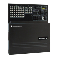
The CCM plugs into slot N in the rear of the AD168
bay. The SensorNet port is located at the top of the
module, directly beneath the yellow dot.
The SensorNet connector contains the six two-wire
positions for data connections to SpeedDomes,
DeltaDomes and SensorNet J-Boxes. The six positions
are labeled N1 through N6 respectively. SensorNet
cables do not have a polarity reference, so each of the
two-wire cable leads can be connected to either of the
two connection points for each N pair.
For appropriate pin positions on SpeedDomes,
DeltaDomes and SensorNet J-Boxes, see the manual for
the device used.
1.
Strip 6mm (.25”) of insulation from each of the
SensorNet leads and insert them into the
appropriate slot pairs on the SensorNet
compression connector (the pairs line up with
positions N1 through N6 on the rear of the CCM).
2.
Tighten the screws on each lead until they are held
firmly in position. Do not over-tighten.
3.
When all necessary leads are attached, plug the
connector into the SensorNet port on the CCM.
!"#
A SensorNet network consists of one or more network
“links”. Each link includes a twisted pair cable, a
SensorNet host (in this case, the AD168 Control Code
Module resident in the AD168 bay), and 1 to 32
SensorNet devices (with the AD168 Matrix
Switcher/Controller system, the devices supported are
SpeedDomes, DeltaDomes or SensorNet J-Boxes).
$ %&#
For proper operation, both ends of
each SensorNet link must be
terminated. This prevents signals
reaching the end of the line from
being reflected back along the line.
All SensorNet devices have a
termination switch or jumper for this
purpose. When in the “terminate”
position, a resistor is placed across
the SensorNet cable connections to
suppress reflected signals.
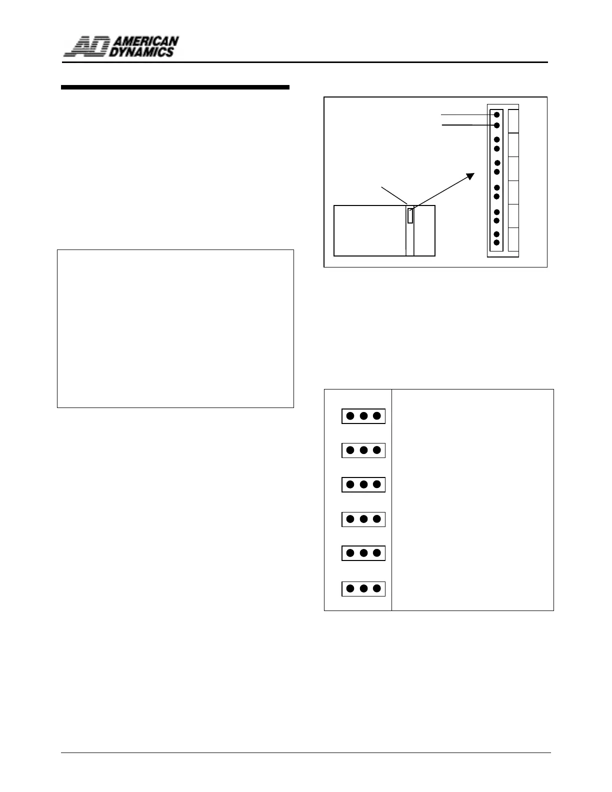
On the AD168 CCM card,
connectors J3 through J8 enable the
user to terminate each of the
SensorNet channels (N1-N6). To
terminate a channel, place the jumper
over the two pins in the “T” position
(the two pins furthest to the right in
Figure 2).
Think of each SensorNet link as a single twisted pair
cable with a terminating resistor at each end. A host and
up to 32 devices are then placed along the cable. If the
host is placed at one end of the cable, it must be
terminated, and can only support one cable branch.
If the host is placed in any intermediate position, it is
not terminated and can support 2 to 4 cable branches. In
this configuration, the last device attached to each cable
branch must be terminated.
N1
N2
N3
N4
N5
N6
AWG 22 Twisted Pair Cable to
SpeedDomes, DeltaDomes and
SensorNet J-Boxes
AD168 Bay (rear)
Slot N for Control
Code Module
Six Position SensorNet Plug-in Connector
U T
J8
CH6
J7
CH5
J6
CH4
J5
CH3
J4
CH2
J3
CH1
 Loading...