8000-0912-01, Rev A AD168 Release 3.0 Supplement 3
4.
Whenever possible, attach devices backbone style,
following the instructions under Backbone link
Guidelines.
!""
To simplify network checkout, attach devices in stages,
one J-Box at a time. Attach all devices associated with
the first link before starting the second link. After
connecting a set of devices, select each one individually
from the surveillance system and confirm that the
device response is correct. If not, correct the problem
before continuing with installation activities.
#.
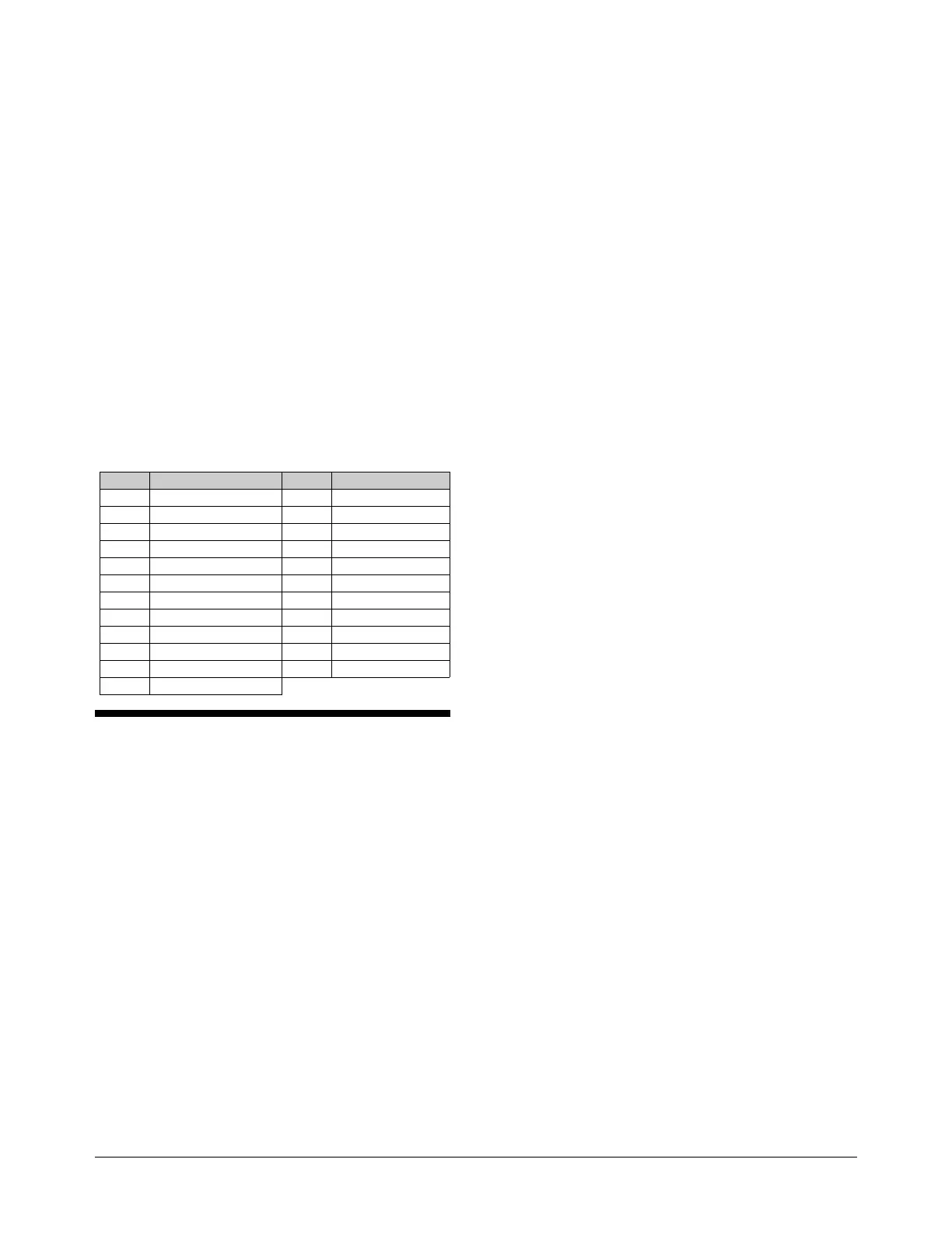
When used in combination with numeric keypad inputs,
the F1 and F2 keys on the AD2078A, AD2079, and
ADTT keyboards accomplish functions related to the
operation of SpeedDome, SpeedDome LT, SpeedDome
Ultra, and DeltaDomes. Following is a list of F1 and F2
combinations and their associated functions.
Keys Function Keys Function
19-F1 Flip Camera 180° 130-F2 Save New Pattern
20-F1 Reset Iris 31-F1 Go to Pattern 1
38-F2 Enter Vert Phase Adj 32-F1 Go to Pattern 2
39-F2 Exit Vert Phase Adj 33-F1 Go to Pattern 3
30-F1 Reset Mode 21-F1 Run Pattern 1
69-F1 Return to Auto Iris/ Focus 22-F1 Run Pattern 2
70-F1 Set Auxiliary 4 OFF 23-F1 Run Pattern 3
71-F1 Set Auxiliary 4 ON 41-F1 Auto Repeat Pattern 1
120-F2 End Pattern Definition 42-F1 Auto Repeat Pattern 2
121-F2 Define Pattern 1 43-F1 Auto Repeat Pattern 3
122-F2 Define Pattern 2 44-F1 Apple Peel
123-F2 Define Pattern 3
'/#
In response to user inquiries, the following section is
included to clarify specific features of AD168 system
operation. This information supplements and/or
supersedes related information included in the system
manuals.
0&
When using S3 system setup software, the user clicks
the Alarms-Alarm speed button to perform entry/editing
of alarm parameters.
After clicking the speed button, a choice list with 11
monitor/contact table names appears. The Manual Table
is used only when a single set of monitor and contact
associations is necessary. Tables 1-10 are used when
multiple sets of monitor/contact associations are used in
combination with Event Timers. Selecting any one of
the 11 tables brings up a screen divided into two
segments:
1.
The larger, left-hand segment is the system alarm
contact table that allows the user to associate up to
1024 alarm contacts with the cameras installed in
the AD168 system. There is only one alarm contact
table in the AD168, and it is displayed for
convenient reference and editing when any of the
11 monitor/contact tables are selected from the
choice list for editing.
2.
The narrow, right-hand segment is the
monitor/contact table selected from the choice list.
This table allows the user to associate monitors
with contacts selected (highlighted) in the system
alarm contact table on the left.
•
Entries made in the right-hand segment become
part of the monitor/contact table selected from the
original choice list.
•
Entries made in the left-hand segment become part
of the system alarm contact table and apply to all
monitor/contact tables.
The left-hand segment should be programmed to
conform to the physical site configuration of alarm
contacts, associated cameras, and other alarm
parameters (dwell times, presets, auxiliaries, title
numbers, and contact links). Editing is required
only if the site configuration changes, or in the
event of errors in previous data entries.
Sets of monitor/contact associations are created for
each monitor/contact table used when defining
Event Timers.
This description replaces corresponding information found on P. 2-24 of
the AD168 System Administrator’s Manual, PN 8000-0935-01, Rev B.
'&
1
“Connect Next” is the function that links a tour entry to
the entry following it. Four selections are available:
“Yes”, “No”, “Salvo”, and “Tour”.
•
If “Yes” is selected, the Connect Next function
calls the next tour entry to the next contiguous
monitor. By doing this, the user is simulating a
salvo.
•
If “No” is selected, the Connect Next function calls
the next tour entry to the monitor originally called
for the tour. By selecting “No” exclusively for the
Connect Next links in a given tour, the user will
see each tour entry appear on the originally called
monitor. Each tour entry will appear for the Dwell
Time assigned to it.
•
If “Salvo” is selected, another pre-programmed
system tour will be called to the monitor originally
called. Each of the other salvo entries will appear
on contiguous monitors.
•
If “Tour” is selected, another pre-programmed
system tour will be called to the monitor originally
called. The selection of “Tour” effectively links
 Loading...