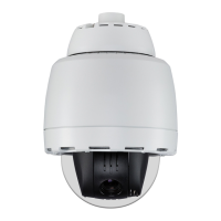
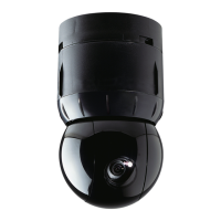
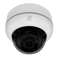
SENSORRAIL IIIE 8200-0593-03, REV. A
SERVICE GUIDE
2 of 34
Theory of Operation
Trolley CPU
The CPU in the trolley filters command data from a
matrix switcher or controller. Movement along the
rail is accomplished by sending an IRIS or FOCUS
command. This command is sent to the dome
camera by the matrix switcher, which the trolley
CPU converts to left and right instructions.
Note: To the matrix switcher, the trolley CPU board
is transparent. However, some commands are
delayed compared to what is typical for a dome
camera’s response.
This section describes the CPU to help you
perform maintenance efficiently. It does not provide
detailed information on internal electronic
components.
Board Layout
Refer to figures on pages 7 and 8.
The CPU board manages all trolley functions. The
main CPU functions and components are as
follows:
• Main connector: Provides power to the motor
and receives data from the encoder and the
dome (RS-422 bi-directional communication).
• Power connector: Receives 27Vdc and RS-
232 data provided by the four sliding collectors.
• Five LEDs: Enable quick diagnostics in case of
technical problems.
• RF 2.4GHz transmitter board: Replaceable by
removing four soldered attachment points.
• RF 2.4GHz emitter connector: Provides power
and composite video signal to RF link emitter.
• BNC connector: Receives composite video
signal from the dome.
• ATMEGA 128 microcontroller: Receives all
external data and drives the motor.
• Electronic brake devices: A relay and a
resistor that slow the motor by applying
resistance to the motor.
• Optical sensors: Detect optical strips at the
beginning and the end of the rail.
• JTAG connector and DIP switches: Used for
factory programming and future features.
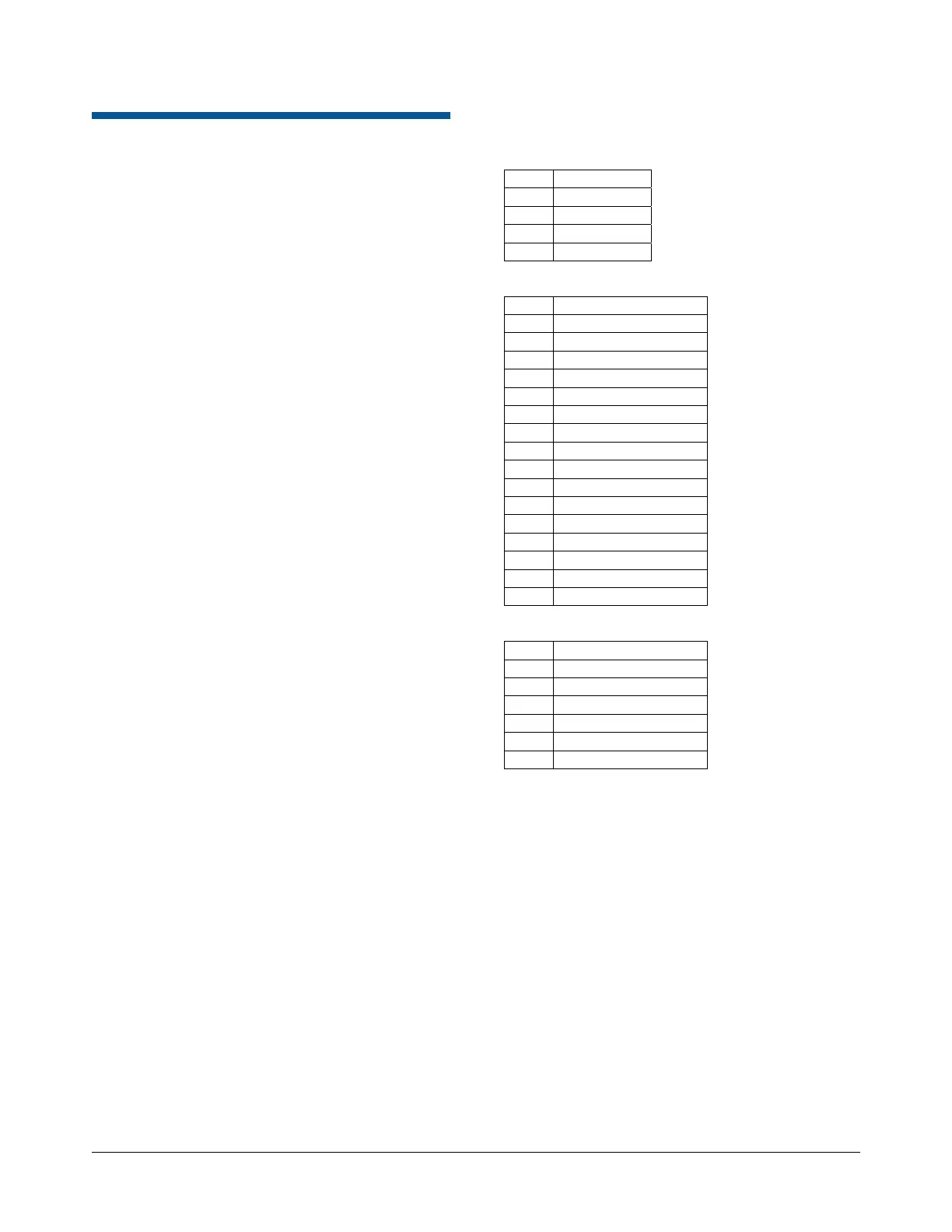
CPU Connections
Power connector (J1)
Pin Function
1 27Vdc
2 0V
3 RS-232 TX
4 RS-232 RX
Main connector (J2)
Pin Function
1 Not used
2 RS-422 TX– to Dome
3 RS-422 TX+ to Dome
4 RS-422 R to Dome
5 RS-422 RX+ to Dome
6 27Vdc to Dome
7 0V to Dome
8 VB channel (encoder)
9 5Vdc to Encoder
10 VA channel (encoder)
11 SC Synchro (encoder)
12 Not used
13 Motor –
14 Temp probe (future)
15 Not used
16 Motor +
Transmitter connector
Pin Function
1 5Vdc
2 GND
3 12Vdc
4 GND
5 Composite video IN
6 GND
 Loading...