SENSORRAIL IIIE ADRL3TRK SERIES 8200-0593-02, REV. A
INSTALLATION GUIDE
2 of 34
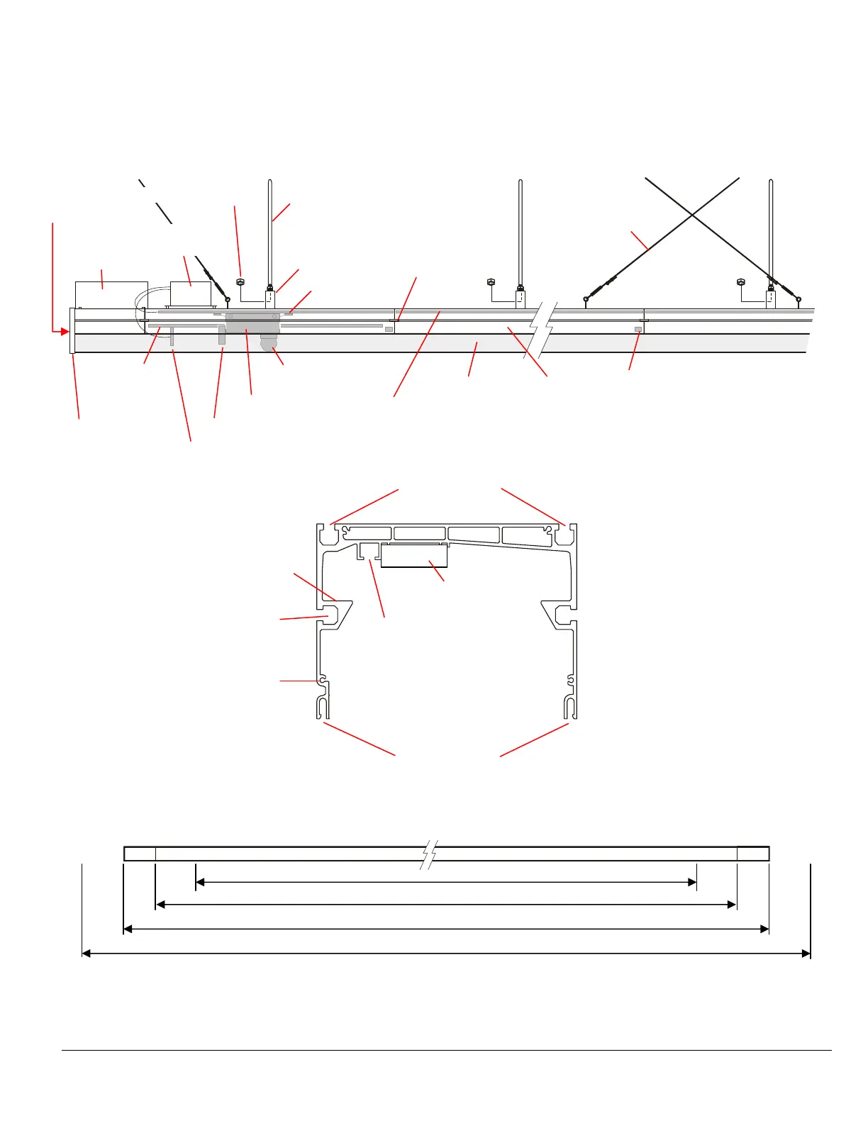
Product Features
Vision area (for surveillance), dead zones (for stopping), and maintenance areas (for servicing)
Side Grooves (2)
for jointing plates
Top Grooves
for jointing plates
Cowling Grooves
Stop Groove
PVC Holder
Rolling Track (2)
Start End of Rail
Bracket Grooves (2)
for Rx Antenna
Vision Area
Vision Area + Two 1.5m (4.9ft) Dead Zones
Vision Area + Two 1.5m (5ft) Dead Zones +Two 30cm (1ft) Light Reduction Sections = Total Length of Rail
Total Length of Rail + Two 0.6m (2ft) Maintenance Areas
Rail
End Cover (2)
RF Rx Antenna
RF Tx Antenna
Camera Trolley
Dome Camera
Collector (4)
Mirrored
Cowling
Rail Section
Jointing Plate
(4 per section)
PVC Holder
w/copper tracks
M8 Threaded Rod
Stirrup
Optical Stop
Label (one at
each end of rail)
Light Reducer
(one at each
Optical Spot Label
one
er rail
Crisscrossed
Anti-Sway
Cables Every
15m (49.2ft)
PowerRail
Module
Start End of Rail
(see below)
M8 Locking Nut
 Loading...