PAGE 4 Pub. No. 11-AC11D2-5
INSTALLER'S GUIDE
7. Table 1 defines maximum total length of low voltage wiring
from outdoor unit, to indoor unit, and to thermostat.
8. Mount the indoor thermostat in accordance with instruction
included with the thermostat. Wire per appropriate hookup
diagram (included in these instructions).
G. COMPRESSOR START UP
After all electrical wiring is complete, SET THE THERMOSTAT
SYSTEM SWITCH IN THE OFF POSITION SO COMPRESSOR
WILL NOT RUN, and apply power by closing the system main
disconnect switch. This will activate the compressor sump heat
(where used). Do not change the Thermostat System Switch
until power has been applied for one (1) hour. Following this
procedure will prevent potential compressor overload trip at the
initial start-up.
H. OPERATIONAL AND CHECKOUT PROCEDURES
Final phases of this installation are the unit Operational and
Checkout Procedures which are found in this instruction on page 8.
To obtain proper performance, all units must be operated and
charge adjustments made in accordance with procedures found
in the Service Facts.
I. ELECTRIC HEATERS
Electric heaters, if used, are to be installed in the air handling
device according to the instructions accompanying the air han-
dler and the heaters.
J. START CONTROL
Some models have quick start components which are factory
installed. For models that do not have factory installed start
components, provisions are made for a field installed start kit
accessory. When adding an accessory, follow the instructions
provided with the kit.
K. OUTDOOR THERMOSTAT
An outdoor thermostat TAYSTAT250B may be field installed.
For data, see wiring diagram attached to unit and instruction
sheet packaged with outdoor thermostat.
L. SEACOAST SALT SHIELD
The 2A7A4 & 2A7A5 models are shipped with a black Seacoast
Salt Shield. The 2A7A2 & 2A7A1 units installed within one mile
of salt water, including seacoasts and inland waterways, require
the addition of BAYSEAC001 (Seacoast Kit) at the time of
installation.
IMPORTANT: See Limited Warranty information in Use
and Care Manual.
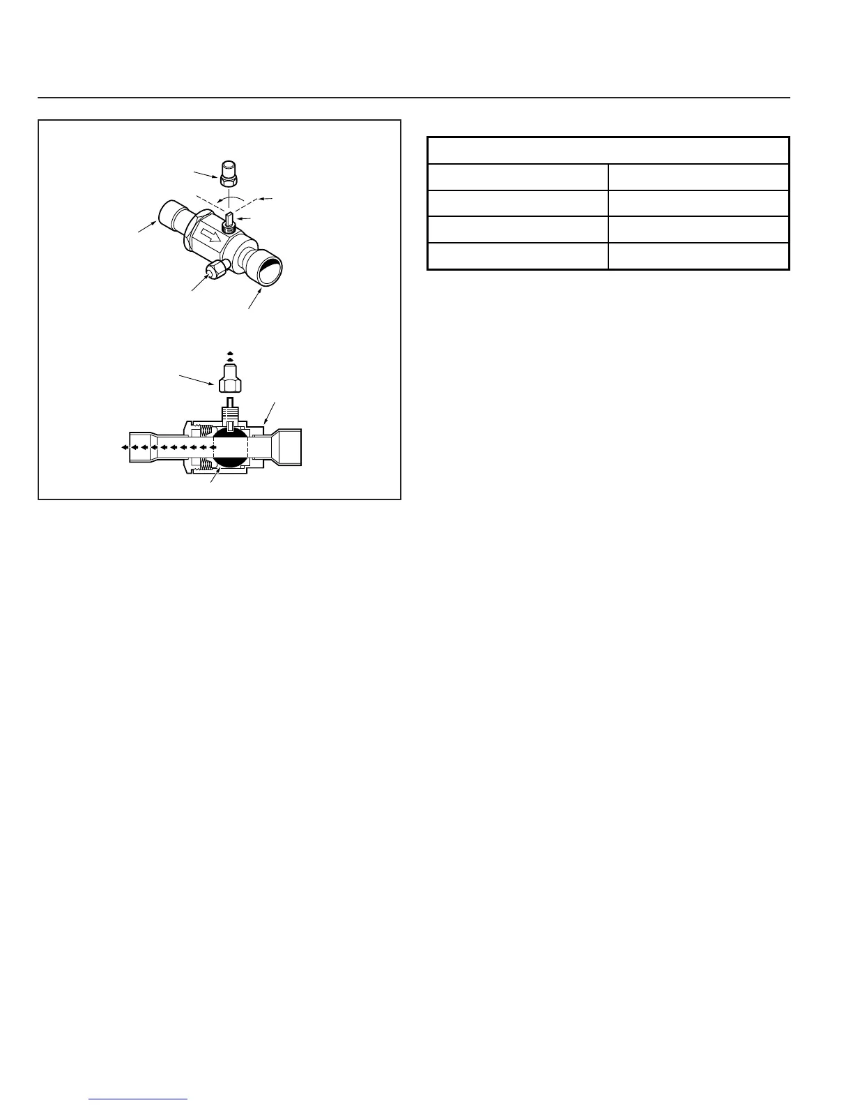
10. Replace liquid service pressure tap port cap and valve stem
cap. These caps MUST BE REPLACED to prevent leaks.
Replace valve stem and pressure tap cap finger tight, then
tighten an additional 1/6 turn.
11. The gas valve can now be opened. Open the gas valve by
removing the shut-off valve cap and turning the valve stem
1/4 turn counterclockwise, using 1/4" Open End or Adjustable
wrench. See Figure 5.
12. The gas valve is now open for refrigerant flow. Replace valve
stem cap to prevent leaks. Again, these caps MUST BE RE-
PLACED to prevent leaks. Replace valve stem and pressure tap
cap finger tight, then tighten an additional 1/6 turn. See Figure 5.
If refrigerant lines are longer than 15 feet and/or a different size
than recommended, it will be necessary to adjust system
refrigerant charge upon completion of installation. See unit
Service Facts.
F. ELECTRICAL CONNECTIONS
▲ WARNIN
:
When installing or servicing
this equipment, ALWAYS exercise basic safety precau-
tions to avoid the possibility of electric shock.
1. Power wiring and grounding of equipment must comply with
local codes.
2. Power supply must agree with equipment nameplate.
3. Install a separate disconnect switch at the outdoor unit.
4. Ground the outdoor unit per local code requirements.
5. Provide flexible electrical conduit whenever vibration trans-
mission may create a noise problem within the structure.
6. The use of color coded low voltage wire is recommended to
simplify connections between the outdoor unit, the thermostat
and the indoor unit.
Table 1 — NEC Class II Control Wiring
CAP
1/4 TURN ONLY
COUNTERCLOCKWISE
FOR FULL OPEN
POSITION
VALVE STEM
GAS LINE CONNECTION
UNIT SIDE
OF VALVE
CAP
BODY
COOLING
CORE
PRESSURE TAP PORT
GAS LINE BALL SERVICE VALVE
5
24 VOLTS
WIRE SIZE MAX. WIRE LENGTH
18 AWG 150 FT
16 AWG 225 FT.
14 AWG 300 FT.