EasyManua.ls Logo

American Standard 2A6H1018-060 - User Manual

American Standard 2A6H1018-060
8 pages
Print Icon
To Next Page IconTo Next Page
Loading...
© 2009 American Standard Heating & Air Conditioning
Since the manufacturer has a policy of continuous product
and product data improvement, it reserves the right to
change design and specifications without notice.
11-BC08D2-5
These instructions do not cover all variations in systems
nor provide for every possible contingency to be met in
connection with installation. All phases of this installa-
tion must comply with NATIONAL, STATE AND LOCAL
CODES. Should further information be desired or should
particular problems arise which are not covered sufficiently for
the purchaser’s purposes, the matter should be referred to your
installing dealer or local distributor.
A. GENERAL
The following instructions cover 2A6H1, 2A6H2, 2A6H4, &
2A6H5 Heat Pump Units.
NOTICE: These outdoor units may be used with indoor
units equipped with Thermostatic Expansion Valve or
Accutron™ Flow Control Check Valve (F.C.C.V.) assembly
for refrigerant flow control only.
Check for transportation damage after unit is uncrated. Report
promptly, to the carrier, any damage found to the unit.
To determine the electrical power requirements of the unit, refer
to the nameplate of the unit. The electrical power available must
agree with that listed on the nameplate.
The Heat Pump has been designed and manufactured to with-
stand and operate in severe winter conditions. However, there
are precautionary steps which should be taken at the time of
installation which will help assure the efficient operation of the
unit. It is recommended that these precautions be taken
for units being installed in areas where snow accumula-
tion and prolonged below freezing temperatures occur.
1. Units should be elevated 3 to 12 inches above the pad or
rooftop, depending on local weather. This additional height will
allow better drainage of snow and ice (melted during defrost cycle)
prior to its refreezing. This should prevent a buildup of ice around
the unit which occurs when unit is not elevated. Insure that
drain holes in unit base pan are not obstructed prevent-
ing draining of defrost water.
2. If possible, avoid locations that are likely to accumulate snow
drifts. If not possible, a snow drift barrier should be installed
around the unit to prevent a buildup of snow on the sides of the
unit and should be of sufficient distance from the unit to prevent
restriction of airflow to and from the unit. Also allow for proper
maintenance space. The barrier should be constructed of mate-
rials which will blend in with the building design.
3. Avoid locating the unit where condensation and freezing of
defrost vapor may annoy the customer. For instance, installing
the unit under a bedroom, kitchen, or picture window may be
annoying to the customer since condensate and fog will occur
during the defrost cycle.
4. Avoid locating the unit under the eaves or other overhead
structures as sizeable icicles may form and the unit may be
damaged by these falling icicles.
B. LOCATION AND PREPARATION OF THE UNIT
1. When removing unit from the pallet, notice the tabs on the
basepan. Remove tabs by cutting with a sharp tool as shown on
page 2, Figure 2, and slide unit off of pallet.
2. The unit should be set on a level support pad at least as large
as the unit base pan, such as a concrete slab.
3. The support pad must NOT be in direct contact with any
structure. Unit must be positioned a minimum of 12" from any
wall or surrounding shrubbery to insure adequate airflow. Clear-
ance must be provided in front of control box (access panels) &
any other side requiring service access to meet National Electri-
cal Code. Also, the unit location must be far enough away from
any structure to prevent excess roof runoff water from pouring
directly on the unit. Do not locate unit(s) close to bedroom(s).
Heat Pumps
INSTALLER'S GUIDE
ALL phases of this installation must comply with NATIONAL, STATE AND LOCAL CODES
5 FT. ABOVE UNIT-UNRESTRICTED
1
2A6H1018-060, 2A6H2018-060,
2A6H4018-060 & 2A6H5024-060
IMPORTANT — This Document is customer property and is to remain with this unit. Please return to service information pack
upon completion of work.
Models:
Question and Answer IconNeed help?

Do you have a question about the American Standard 2A6H1018-060 and is the answer not in the manual?

Summary

GENERAL INSTALLATION GUIDELINES

Unit Placement & Snow;Ice Precautions

Precautions for unit placement in areas with snow, ice, or potential condensation issues.

LOCATION AND PREPARATION OF THE UNIT

Outdoor Unit Setup & Clearances

Guidelines for setting the unit on a pad, ensuring airflow, and maintaining clearances from structures.

REFRIGERANT LINE INSTALLATION

Line Length, Lift, and Routing

Guidelines for top discharge clearance, line length, lift, and routing refrigerant tubing.

ACCUTRON FLOW CONTROL VALVE

Orifice Size Check and Adjustment

Instructions on checking and changing the orifice size for system performance.

REFRIGERANT LINE BENDING AND SECURING

Brazing, Bends, and Noise Prevention

Best practices for running and securing refrigerant lines, including bend considerations and noise prevention.

SERVICE VALVE OPERATION AND BRAZING

Brass Valve Operation & Brazing Precautions

Operation and warnings for brass liquid and gas line service valves; brazing procedures.

LEAK CHECK AND SYSTEM EVACUATION

Leak Detection & Evacuation Steps

Procedures for leak checking refrigerant lines and evacuating the system to specified micron levels.

REFRIGERANT CHARGING AND LINE SETTING

System Charging & Line Valve Procedures

Steps for charging the system with refrigerant and setting line valves.

ELECTRICAL CONNECTIONS AND DEFROST CONTROL

Wiring, Grounding & Defrost Operation

Guidelines for wiring, grounding, disconnects, and defrost control operation.

COMPRESSOR START-UP AND SYSTEM CHECKS

Compressor Start-up & Operational Checkout

Procedures for compressor start-up, sump heat, and system operational checks.

ACCESSORY INSTALLATION AND SHIELDING

Heaters, Start Kits, Thermostats & Shields

Guidance on installing electric heaters, start kits, outdoor thermostats, and salt shields.

UNIT OUTLINE DRAWINGS AND SPECIFICATIONS

Model Dimensions and Outline Data

Provides outline drawings and dimensional data for various heat pump models.

MOUNTING HOLE LOCATION DETAILS

Base Mounting Hole Patterns

Diagrams showing mounting hole locations for different unit bases.

FINAL INSTALLATION CHECKLIST

System Checkout Procedure List

A comprehensive checklist for verifying proper installation and system operation.

TROUBLESHOOTING SYSTEM FAULTS

Troubleshooting Chart and Causes

A chart to diagnose system faults based on symptoms and identify potential causes.

Overview

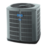
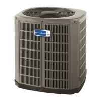
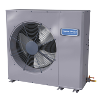
This document is an installer's guide for American Standard Heat Pumps, specifically models 2A6H1018-060, 2A6H2018-060, 2A6H4018-060, and 2A6H5024-060. It provides comprehensive instructions for the installation, operation, and maintenance of these units, emphasizing compliance with national, state, and local codes.

Function Description:

The American Standard Heat Pump is an outdoor unit designed for heating and air conditioning. It works in conjunction with indoor units equipped with either a Thermostatic Expansion Valve or an Accutron™ Flow Control Check Valve (F.C.C.V.) assembly for refrigerant flow control. The unit is designed to withstand and operate efficiently in severe winter conditions, with specific precautions recommended for areas prone to snow accumulation and prolonged below-freezing temperatures. A key feature is the demand defrost control, which measures outdoor ambient and coil temperatures to determine the need for defrost cycles, optimizing efficiency.

Important Technical Specifications:

  • Refrigerant Lines:
    • Maximum length of refrigerant lines from outdoor to indoor unit: 60 feet.
    • Maximum lift (suction line, if outdoor unit is mounted above air handler): 60 feet.
    • Maximum lift (liquid line, if air handler is mounted above condensing unit): 60 feet.
    • The gas line must always be insulated.
    • The units are factory charged with the system charge required for 15 feet of connecting line. Final refrigerant charge adjustment is necessary based on specific installation length.
  • Electrical Requirements:
    • Power wiring and grounding must comply with local codes.
    • A separate disconnect switch is required at the outdoor unit.
    • Low voltage wiring: No. 18 AWG minimum conductor.
    • Maximum total length of low voltage wiring (outdoor unit to indoor unit and thermostat):
      • 18 AWG: 150 FT
      • 16 AWG: 225 FT
      • 14 AWG: 300 FT
  • Defrost Control:
    • Utilizes two sensors: one for outdoor ambient temperature and one for outdoor coil temperature. The difference (delta-T) determines the need for defrost. The coil sensor also terminates the defrost cycle.
    • Fault conditions are indicated by a flashing light on the defrost control board. Normal operation shows the LED flashing once per second.
  • Physical Dimensions (Refer to Outline Drawing and Table on Page 6):
    • Various base sizes (Base 2, 3, 4) with corresponding dimensions for different models.
    • Overall dimensions (A, B, C) vary by model, ranging from approximately 651 mm (25-5/8 in) to 1045 mm (41-1/8 in) in height (A), 724 mm (28-1/2 in) to 946 mm (37-1/4 in) in width (B), and 651 mm (25-5/8 in) to 870 mm (34-1/4 in) in depth (C).
    • Liquid line service valve connections (E) are typically 1/4" or 5/16" SAE flare pressure tap fittings.
    • Gas line service valve connections (D) vary from 5/8" to 1-1/8" ID female brazed connections.
    • Minimum clearances: 5 feet above the unit (unrestricted), 12 inches from any wall or surrounding shrubbery on two sides for adequate airflow. Clearance must also be provided in front of control box and other service access sides.

Usage Features:

  • Installation Location:
    • Units should be elevated 3 to 12 inches above the pad or rooftop, depending on local weather, to allow better drainage of snow and ice during defrost cycles and prevent ice buildup. Drain holes in the unit base pan must remain unobstructed.
    • Avoid locations prone to snow drifts; if unavoidable, install a snow drift barrier at a sufficient distance to prevent airflow restriction and allow maintenance space.
    • Avoid locating the unit under bedroom, kitchen, or picture windows to prevent annoyance from condensation and freezing defrost vapor.
    • Avoid placement under eaves or other overhead structures where falling icicles could damage the unit.
    • The support pad must be level and at least as large as the unit base pan, and not in direct contact with any structure.
    • If roof-mounted, ensure the roof can support the unit's weight, and use isolation to prevent vibration transmission.
  • Refrigerant Line Installation:
    • All joints must be brazed, not soldered.
    • Pressure taps are provided on service valves for compressor suction and liquid pressures.
    • Refrigerant lines should be routed to minimize sharp 90-degree bends.
    • Isolation type hangers should be used when fastening lines to building structures (floor joists, framing, stud spaces, enclosed ceilings) to prevent noise from vibration transmission.
  • Service Valve Operation:
    • Brass liquid and gas line service valves are factory-shipped in the seated position.
    • Liquid line valve: Turn stem counterclockwise until it contacts the rolled edge (no torque required).
    • Gas line ball service valve: Full open with a 1/4 turn counterclockwise.
    • CAUTION: When brazing, remove the pressure tap port valve core and wrap a wet rag around the valve body to prevent heat damage. Ensure no moisture enters the port. Keep flame off the basepan.
  • System Evacuation:
    • After leak checking, evacuate refrigerant lines and indoor coil to no higher than 350 microns.
    • If the gauge rises above 500 microns in one minute, evacuation is incomplete or there's a leak.
  • Electrical Connections:
    • Use flexible electrical conduit to prevent noise from vibration transmission.
    • Use color-coded low voltage wire.
    • Mount indoor thermostat according to instructions.
  • Compressor Start-up:
    • Set the thermostat system switch to OFF and apply power for one hour before changing the switch to allow the compressor sump heat to activate, preventing potential overload trips.
  • Outdoor Thermostat:
    • An optional TAYSTAT250B outdoor thermostat may be field installed.
  • Seacoast Salt Shield:
    • Models 2A6H4 & 2A6H5 are shipped with a black Seacoast Salt Shield.
    • Models 2A6H2 & 2A6H1 installed within one mile of saltwater (including seacoasts and inland waterways) require the addition of BAYSEAC001 (Seacoast Kit).

Maintenance Features:

  • Accutron™ Flow Control Valve:
    • If the indoor unit uses an Accutron™ orifice and check valve assembly, the orifice size may need to be changed based on the outdoor model's nameplate specification to achieve rated performance. The outdoor unit ships with the correct orifice and a stick-on label.
  • Leak Check:
    • After brazing, pressurize the system with dry nitrogen to 350-400 psi and use soap bubbles to check all field joints for leaks.
  • Defrost Control Checkout:
    • Normal operation: LED flashes once/second, 24V AC between R & B, and 24V AC between Y & B (when operating).
    • Defrost initiation: Short FRC_DFT pin to TEST_COMMON pin for two seconds.
    • Fault identification: A flashing light on the defrost control indicates a fault. Refer to the service manual if the light flashes more than once per second or not at all.
  • Troubleshooting Chart:
    • A comprehensive chart is provided to diagnose system faults related to refrigerant circuit (e.g., head pressure, suction pressure, liquid floodback, coil frosting) and electrical issues (e.g., compressor/fan won't start, compressor cycles on IOL, defrost problems). It lists primary and secondary causes for each fault.
  • General Maintenance:
    • Regularly check for transportation damage.
    • Ensure all electrical connections are tight.
    • Observe outdoor fan for clearance and smooth operation.
    • Verify indoor coil drain line drains freely.
    • Ensure supply registers and return grilles are open and unobstructed.
    • Confirm return air filter is installed.
    • Check thermostat accuracy and adjust as needed.
    • Verify correct indoor blower motor speed tap.
    • Operate the complete system in each mode to ensure safe operation.

American Standard 2A6H1018-060 Specifications

General IconGeneral
BrandAmerican Standard
Model2A6H1018-060
CategoryHeat Pump
LanguageEnglish

Related product manuals