Do you have a question about the American Standard 2A7B3018-1000A and is the answer not in the manual?
Details on operating brass liquid and gas line service valves, including ball type and general procedures.
Instructions for brazing refrigerant lines, including preparation, purging, and techniques.
Procedure to check field brazed connections for leaks using dry nitrogen and soap bubbles.
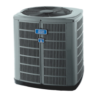
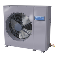
This document is an installer's guide for American Standard Condensing Units, specifically models 2A7B3018-060A1000A. It provides comprehensive instructions for the installation, operation, and maintenance of these outdoor units, emphasizing compliance with national, state, and local codes. The guide is intended for individuals with adequate electrical and mechanical experience, as attempts to repair central air conditioning products without proper knowledge can result in personal injury or property damage.
The American Standard Condensing Units are designed to work as part of a central air conditioning system, typically paired with an approved matched indoor coil or air handler. Their primary function is to facilitate the cooling process by compressing and circulating refrigerant, releasing heat outdoors, and preparing the refrigerant for the indoor cooling cycle. The units are factory charged with refrigerant (R-22, as indicated by the subcooling charging table) and are designed for optimal efficiency and performance when installed as part of a complete American Standard matched system. The guide details the process of connecting the outdoor unit to the indoor unit via refrigerant lines, evacuating the system, and adjusting the refrigerant charge to ensure proper operation.
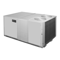
The installation process begins with careful consideration of the unit's location. The guide specifies that the unit should be set on a level support pad at least as large as its base pan, such as a concrete slab, and must not be in direct contact with any structure. Adequate clearance is crucial for proper airflow and service access; a minimum of 12 inches from walls or shrubbery is required, with the top discharge area needing at least five feet of unrestricted space above the unit. This ensures efficient heat dissipation and prevents obstruction of the fan. When mounting on a roof, the roof must be able to support the unit's weight, and proper isolation is recommended to prevent sound transmission to the building structure. Sound transmission through air and refrigerant lineset is also a key consideration, advising placement away from noise-sensitive areas like bedrooms.
The guide provides detailed instructions for installing refrigerant lines, including how to remove basepan tabs for easier handling. It emphasizes the importance of using approved matched indoor and outdoor systems for maximum efficiency and reliability. The maximum recommended length for refrigerant lines from the outdoor to indoor unit is sixty feet. For installations where the outdoor unit is mounted above the air handler, the maximum lift for the suction line should not exceed sixty feet. Conversely, if the air handler is above the condensing unit, the maximum liquid line lift should not exceed sixty feet.
The document describes the operation of the brass liquid and gas line service valves, which are factory-shipped in a seated or closed position to retain the factory charge. These valves feature pressure tap service ports that open only to the field brazing side when the valve is in the seated position, allowing for brazing without losing the factory charge. Extreme caution is advised when opening these valves, instructing installers to turn the valve stem counterclockwise only until it contacts the rolled edge, without applying excessive torque. The gas line ball service valve, specifically, is full open with a 1/4 turn.
Brazing refrigerant lines is a critical step, requiring the removal of plugs from copper stub tubes and cleaning surfaces prior to brazing. Precautions are outlined to prevent heat damage to the pressure tap valve core during brazing, such as removing the core and wrapping a wet rag around the valve body. A dry nitrogen purge and brazing alloy without flux are specified for brazing field lines to factory connections, ensuring a clean and leak-free joint. After brazing, a leak check is mandatory, pressurizing the system with dry nitrogen to 350-400 psi and using soap bubbles or other methods to confirm all field joints are leak-free.
System evacuation is another crucial step, performed after the leak check and before opening the gas and liquid line valves. The system must be evacuated until a micron gauge reads no higher than 350 microns. If the gauge pressure rises above 500 microns within one minute, it indicates incomplete evacuation or a system leak. Once evacuation is complete, the refrigerant lines and indoor coil are charged with vapor from an HCFC-22 cylinder. The guide strictly states, "DO NOT VENT REFRIGERANT INTO THE ATMOSPHERE." Finally, the liquid line shut-off valve is opened using an Allen wrench, and all caps (pressure tap port and valve stem) must be replaced and tightened to prevent leaks.
Electrical connections are also covered, stressing compliance with national, state, and local codes. The unit requires a dedicated electrical circuit, and all wiring must be properly sized and secured. The guide includes a troubleshooting chart for common electrical and refrigerant circuit faults, aiding in diagnosis and repair.
The installer's guide provides essential information for initial system setup and verification, which contributes to long-term maintenance. The "Checkout Procedure" section lists a comprehensive checklist to ensure the entire system is functioning correctly after installation. This includes verifying that refrigerant lines are leak-checked, properly insulated, secured, and isolated. Passages through masonry must be sealed, and all electrical connections must be tight. The outdoor fan's operation should be observed for clearance and smooth running, and the indoor coil drain line must drain freely.
Further checks involve ensuring supply registers and return grilles are open and unobstructed, the return air filter is installed, and the thermostat thermometer is accurate and adjusted per instructions. The correct speed tap for the indoor blower motor must be verified, and the complete system should be operated in each mode to ensure safe operation.
For refrigerant charge adjustment, the guide details a subcooling charging method for cooling above 55°F outdoor ambient temperatures. This method is recommended for systems with indoor TXVs (Thermostatic Expansion Valves). To achieve best results, the indoor temperature should be maintained between 70°F and 80°F. The system must operate for a minimum of 20 minutes to stabilize before accurate measurements can be made. Installers need to measure liquid line temperature and refrigerant pressure at service valves, determine total refrigerant line length and height (lift), and identify the design subcool charging temperature from the unit nameplate. Using the provided subcooling charging table, refrigerant can be added or removed to match the table values, ensuring optimal system performance. Corrections for line length and rise are also provided in a separate table, allowing for precise charge adjustments.
The guide also touches upon the importance of regular maintenance by mentioning the need to check and replace the return air filter, which is a common maintenance task for homeowners. While not explicitly detailing routine maintenance schedules, the thorough installation and checkout procedures outlined in the guide lay the groundwork for a well-functioning system that will require less corrective maintenance over its lifespan. The emphasis on proper installation, leak checks, and charge adjustments directly contributes to the unit's reliability and efficiency, reducing the likelihood of future issues.
| Model Number | 2A7B3018-1000A |
|---|---|
| Category | Heat Pump |
| Brand | American Standard |
| Cooling Capacity (BTU/h) | 18000 |
| Heating Capacity (BTU/h) | 18000 |
| SEER Rating | 16 |
| Refrigerant Type | R-410A |
| Voltage | 208/230 |
| Phase | 1 |
| Compressor Type | Single-Stage |
| Stages | 1 |
| Sound Level (dBA) | 72 |
| Cooling Capacity | 1.5 tons |
| Heating Capacity | 1.5 tons |