SSAAFFEETTYY WWAARRNNIINNGG
Only qualified personnel should install and service the equipment. The installation, starting up, and servicing of heating, ventilating, and air-conditioning
equipment can be hazardous and requires specific knowledge and training. Improperly installed, adjusted or altered equipment by an unqualified person
could result in death or serious injury. When working on the equipment, observe all precautions in the literature and on the tags, stickers, and labels that
are attached to the equipment.
June 2022 1111--BBCC4466DD11--11AA--EENN
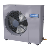
Side Discharge HP Models
For coastal applications where units are installed within one (1) mile of salt water, epoxy coated models are recommended. These models
have an 8 week lead time after order.
EEppooxxyy CCooaatteedd MMooddeell
4A6L5024N1000A
4A6L5030N1000A
4A6L5036N1000A
4A6L5042N1000A
4A6L5048N1000A
4A6L5024N1COTA
4A6L5030N1COTA
4A6L5036N1COTA
4A6L5042N1COTA
4A6L5048N1COTA
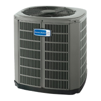
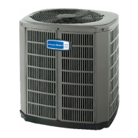
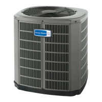
NNoottee:: “Graphics in this document are for representation
only. Actual model may differ in appearance.”
Installer’s Guide