PAGE 4 Pub. No. 11-AC14D1-6
INSTALLER'S GUIDE
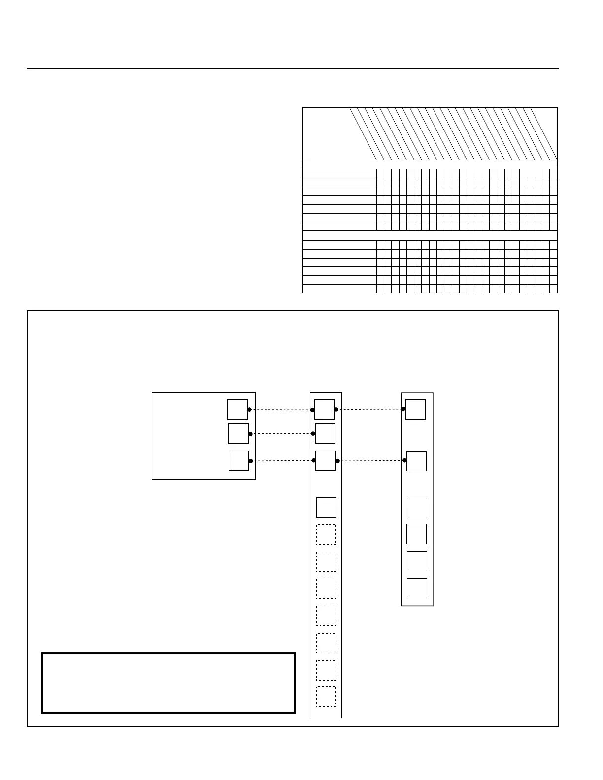
REFRIGERANT CIRCUIT
Liquid Pressure Too High
Liquid Pressure Too Low
Suction Pressure Too High
Suction Pressure Too Low
Liquid Refrig. Floodback TXV System
I.D. Coil Frosting
Compressor Runs Inadequate or No Cooling
ELECTRICAL
Compressor & O.D. Fan Do Not Start
Compressor Will Not Start But O.D. Fan Runs
O.D. Fan Won’t Start
Compressor Hums But Won’t Start
Compressor Cycles on IOL
I.D. Blower Won’t Start
SYSTEM FAULTS
P - Primary Causes S - Secondary Causes
P
P
P
S
S
PS
S
S
S
S
P
S
S
S
P
P
P
S
S
S
S
S
S
S
P
P
P
S
P
P
S
S
S
P
P
P
P
P
P
P
P
P
P
S
S
S
S
P
P
PP
P
S
S
PSPSS S S S
S
S
P
P
P
P
P
S
P
P
POWER SUPPLY
HIGH VOLTAGE WIRING
COMPR. IOL
RUN CAPACITOR
START CAPACITOR
START RELAY
CONTACTOR CONTACTS
LOW VOLTAGE WIRING
CONTROL TRANSFORMER
CONTACTOR COIL
LOW VOLTAGE FUSE
STUCK COMPRESSOR
INEFFICI
ENT COMPRESSOR
REFRIGERANT UNDERCHARGE
REFRIGERANT OVERCHARGE
EXCESSIVE EVAP. LOAD
NONCONDENSABLES
RESTRICTED O.D. AIRFLOW
O.D. AIR RECIRCULATION
TXV STUCK OPEN
SUPERHEAT
RESTRICTED I.D. AIRFLOW
REF. CIRCUIT RESTRICTIONS
O.D. FAN SPEED SWITCH
TROUBLESHOOTING CHART — WHAT TO CHECK
B
BK
Y2
Y1
O
R
D
W1
W3
G
W2
B
D
B
R
D
X2
Y2
Y1
O
AccuLink™
COMFORT
CONTROL
24VAC HOT
24VAC
Common
DATA
AccuLink™
INDOOR
UNIT
AccuLink™
OUTDOOR
UNIT
FIELD WIRING DIAGRAM
COMMUNICATING INDOOR UNIT – COMMUNICATING OUTDOOR UNIT
6
main disconnect switch. This will activate the compressor sump
heat (where used). Do not change the AccuLink™ control switch
until power has been applied for one (1) hour. Following this
procedure will prevent potential compressor overload trip at the
initial start-up.
G. OPERATIONAL AND CHECKOUT PROCEDURES
Final phases of this installation are the unit Operational and
Checkout Procedures which are found in this instruction on
page 7. To obtain proper performance, all units must be operated
and charge adjustments made in accordance with procedures
found in the Service Facts.
NOTE: Perform a final unit inspection to be sure that factory
tubing has not shifted during shipment. Adjust tubing if necessary
so tubes do not rub against each other when the unit runs. Also be
sure that wiring connections are tight and wire routing is secure.
H. SEACOAST SALT SHIELD
BAYSEAC001 (Seacoast Kit) is available for application on units
installed within one mile of salt water, including seacoasts and
inland waterways.
I. TROUBLESHOOTING CHART
NOTE: For non-communicating systems use
24-volt harness accessory BAYACHP024A.
 Loading...