EasyManua.ls Logo

American Standard 50M61-495 User Manual

American Standard 50M61-495
51 pages
To Next Page IconTo Next Page
Page #1 background imageLoading...
Page #1 background image
1
Gas Furnace Silicon
Nitride Ignitor Models
Gas Furnace Silicon
Nitride Ignitor Models
Single and Two Stage Models
Variable Speed Vent Models
Variable Speed Blower Motor
Test Procedures
Direct Vent
Single and Two Stage Models
Variable Speed Vent Models
Variable Speed Blower Motor
Test Procedures
Direct Vent
© 2001 American Standard Inc. All rights reserved.

Table of Contents

Question and Answer IconNeed help?

Do you have a question about the American Standard 50M61-495 and is the answer not in the manual?

American Standard 50M61-495 Specifications

General IconGeneral
BrandAmerican Standard
Model50M61-495
CategoryControl Unit
LanguageEnglish

Summary

IFC Diagnostic Codes

Diagnostic Codes

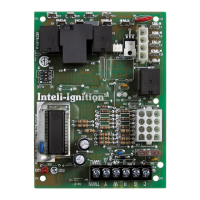
Lists LED flash patterns and their meanings for IFC.

Model Nomenclature

Silicon Nitride Ignitor

Component Identification - Single Stage 80% Upflow/Horizontal

Component Identification - Single Stage 90% Upflow/Horizontal

Integrated Furnace Control CNT2854 – Superseded to CNT03076

Integrated Furnace Control – CNT03076

Single Stage 50A65-474 Sequence of Operation

Wiring Schematic - Single Stage 80% and 90%

Component Identification - Two Stage 80% Upflow/Horizontal

Integrated Furnace Control – CNT03077

Two Stage 50M61-495 Sequence of Operation

Wiring Schematic - Two Stage Heat (White-Rodgers 50M61-495 Series Integrated Furnace Control)

Component Identification - 80% Two Stage/Two Speed Vent Motor and Variable Speed Indoor Motor

Integrated Furnace Control – CNT03078

Two Stage Variable Speed Sequence of Operation

Wiring Schematic - Two Stage Variable Speed Indoor Blower

Component Identification - Two Stage 90% Variable Speed Vent Motor and 4 Speed Indoor Motor

Integrated Furnace Control – CNT2871

Variable Speed Vent Motor

How Does It Learn?

Explains the adaptive learning routine of the variable speed vent motor.

Two Stage 50V65 Sequence of Operation

Wiring Schematic - Two Stage Heat/Variable Speed Vent Motor/Std. Indoor Blower

Component Identification - Two Stage 90% Variable Speed Vent Motor and Variable Speed Indoor Blower

Integrated Furnace Control – CNT02536

Two Stage 50A61 Sequence Of Operation

Wiring Schematic - Two Stage Variable Speed Vent Motor and Blower

Two Stage V/S Vent and V/S Blower Motor Models

Sequence of Operation

Details the operational steps for V/S vent and blower motors.

White-Rodgers Self Diagnostic Features

Fault Diagnostic

Lists fault codes indicated by LED flashes.

Ignition Control Flash Codes

Measuring Variable Speed Vent Motor RPM

Measurement Procedures and Specifications

Provides procedures, formulas, and RPM ranges for measurement.

Diagnosing the V/S Vent Motor with the V/S Troubleshooter

Diagnosing the V/S Vent Motor/Manual Method

Check IFC Green LED Status

Verifies the status of the IFC's green LED.

Perform Jumper Tests

Guides through jumper connections for motor testing.

Verify Motor Lead Voltage

Checks for the presence of 120 VAC at motor leads.

Verify High Speed Operation

Checks if the motor reaches high speed.

Check DC Voltage at Pins

Measures DC voltage between specific pins.

ECM™ 2 Variable Speed Furnace Motor Quick Check

Blower Motor Will Not Run

Provides steps to diagnose why the blower motor does not run.

Manifold Pressure Settings

Furnace Pressure Switch Settings

Related product manuals