M965016 REV.1.6
7415.101
7420.101
Certified to comply with ANSI A112.18.1
Installation
Instructions
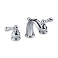
MONOBLOCK LAVATORY
FAUCET with
Speed Connect™ Drain
Adjustable Wrench Screwdriver Channel Locks
Recommended tools
7420.101
7415.101
Series
1
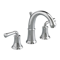
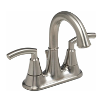
PORTSMOUTH™
To ensure that your installation proceeds smoothly-please read these instructions carefully
before you begin.
Congratulations on purchasing your American Standard
faucet with Speed Connect drain, a feature found only
on American Standard faucets.
*Your new American Standard faucet is designed to work only with the Speed Connect drain.
Speed Connect Drain*
• Fewer parts, installs in less time
• Never needs adjustment
• Guaranteed to seal properly the first time, every time.
COLLAR ON
MOUNTING NUT
8
2
4
3
1
1
8
1
INSTALL FAUCET
7420.101 & 7415.101
Turn off hot and cold water
supplies before beginning.
CAUTION
GROOVE
(FAUCET
BASE)
MOUNTING SURFACE
6
4
7
5
Installation less ESCUTCHEON PLATE:
Seat SEAL (1) into under side of FAUCET BASE (2).
Feed FAUCET SUPPLIES (3), MOUNTING STUD (4) and DRAIN
CABLE ASSEMBLY (8) through the mounting hole of lavatory or
mounting surface. Fig. B.
From below, push GASKET (7) and RETAINING WASHER (5) onto
MOUNTING STUD (4). Secure Faucet with MOUNTING NUT (6),
pulling faucet to front of sink, so SUPPLIES (3) rests against
mounting hole. Before final tightening, make sure collar on
MOUNTING NUT (6) is seated into RETAINING WASHER (5).
Fig. C .
Adjust Faucet so that it is centered. Tighten MOUNTING NUT (6)
to complete faucet mounting.
Fig. C.
Fig. B.
Fig. A.
Installation with ESCUTCHEON PLATE: Apply a light bead of plumbers putty
to underside of ESCUTCHEON PLATE (8) if mounting surface is uneven. Place ESCUTCHEON
PLATE (8) onto sink or mounting surface.
Feed FAUCET SUPPLIES (3), MOUNTING
STUD (4) and DRAIN CABLE ASSEMBLY (8) through
ESCUTCHEON PLATE (8) and
mounting hole of lavatory or mounting surface.
Fig. A.
PUTTY
IF REQUIRED