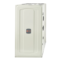
Do you have a question about the American Standard S9V2B080D4VSAB and is the answer not in the manual?
Lists the contents of the S9V2-VS document pack, including quantity and description of each item.
Crucial safety measures and precautions that must be followed during installation, servicing, and operation.
Manufacturer's responsibility disclaimer and recommendations for installation compliance and site inspection.
Specifies required clearances to combustible materials and placement considerations for furnace installation.
Provides dimensional drawings for upflow furnace cabinets across different sizes (B, C, D).
Provides dimensional drawings for downflow furnace cabinets across different sizes (B, C).
Instructions for removing the front panel of the S-Series furnace using a specific tool.
Guidelines for installing the furnace in horizontal attic, crawlspace, or hanging positions.
Details on connecting the gas supply, including important considerations for conversion and piping requirements.
General and specific requirements for furnace venting, including materials and configurations.
Procedure to check furnace gas flow rate (CFH) and compare it to the nameplate rating.
Step-by-step guide for adjusting manifold pressure for 1st and 2nd stage gas heat.
Information on adjusting furnace input ratings based on installation altitude.
Guidelines for connecting supply and return air ductwork to the furnace, including vibration reduction.
Guidance on filter placement and sizing for typical upflow return air filter installations.
Information on filter placement and sizing for typical downflow return air filter installations.
Wiring diagrams for connecting thermostats, outdoor units, and IFC for various furnace and cooling/HP configurations.
Wiring instructions for systems utilizing communicating controls with non-communicating furnaces.
Instructions for installing condensate drains for upflow furnaces in vertical positions.
Guidelines and recommendations for installing condensate drains for furnaces in horizontal positions.
Key checks and inspections required before initiating furnace start-up.
Detailed steps for the initial lighting and burner ignition sequence of the furnace.
Procedures for adjusting and verifying the operation of safety controls like limit switches.
Approved venting configurations for upflow and horizontal left furnace orientations.
Approved venting configurations for horizontal right and downflow furnace orientations.
Instructions for modifying the furnace for different upflow venting configurations.
Instructions for modifying the furnace for different downflow venting configurations.
Procedure for installing the condensate trap assembly and ensuring proper drain operation.
Overview of the IFC menu structure for system configuration and settings.
Explanation of the system status codes displayed on the IFC, including airflow and mode indicators.
Procedure for entering and using the furnace's run test mode.
List and descriptions of display codes for the integrated furnace control.
Procedures for viewing, clearing fault codes, and resetting factory defaults on the IFC.
Detailed operational sequence for the furnace during 1st stage gas heating.
Detailed operational sequence for the furnace during 2nd stage gas heating.
Operational sequence for the furnace during single-stage cooling mode.
Operational sequence for the furnace during two-stage cooling mode.
Explanation of the inducer's self-learning routine to optimize operating speed for each heat stage.
| Model Number | S9V2B080D4VSAB |
|---|---|
| Brand | American Standard |
| Category | Furnace |
| Type | Gas |
| Heating Capacity | 80, 000 BTU |
| Stages | Two-stage |
| Blower Motor | Variable-speed |
| Ventilation | Direct vent |
| Warranty | 10 years limited warranty on parts |


 Loading...