EasyManua.ls Logo

American Standard *UD Series User Manual

American Standard *UD Series
70 pages
To Next Page IconTo Next Page
Page #1 background imageLoading...
Page #1 background image
1
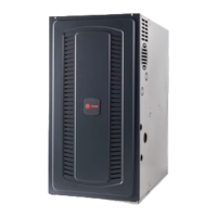
40” Residential Gas
Furnace Operation
40” Residential Gas
Furnace Operation
Model Evolution/Nomenclature
Heating Sequence of Operation
Schematics
Ignition Systems
Service/Troubleshooting
Model Evolution/Nomenclature
Heating Sequence of Operation
Schematics
Ignition Systems
Service/Troubleshooting
© American Standard Inc. 1999

Table of Contents

Question and Answer IconNeed help?

Do you have a question about the American Standard *UD Series and is the answer not in the manual?

American Standard *UD Series Specifications

General IconGeneral
BrandAmerican Standard
Model*UD Series
CategoryFurnace
LanguageEnglish

Summary

White-Rodgers Integrated Furnace Controls – 50A50 & 50A51 Series

White-Rodgers Self Diagnostic Features – 50A50/50A51 Series

White-Rodgers Integrated Furnace Control Timing

White-Rodgers 50A50/50A51 Fault Diagnostics

System Lockout (Loss Of Flame)

Details conditions leading to system lockout due to loss of flame and reset procedures.

Pressure Switch Problem

Troubleshooting pressure switch issues in variable-speed systems.

White-Rodgers 50A55-571/-474 Self Diagnostic Features

Single Stage 50A50 and 50A55 Sequence of Operation

Wiring Schematic

Single Stage (White-Rodger's 50A50 and 50A55 Series Integrated Furnace Controls)

Diagram illustrating single-stage furnace wiring connections.

Two Stage Heat (White-Rodgers 50A51 Series Integrated Furnace Control)

Diagram showing wiring for two-stage heat operation.

Two Stage Variable Speed (White-Rodgers 50A51 and 50A61 Series Integrated Furnace Controls)

Wiring diagram for two-stage variable speed furnace operation.

Version 1 Radiant Sense Control

Wiring diagram for the 50A52-100 Version 1 radiant sense control.

Version 2 Radiant Sense Control

Wiring diagram for the 50A52-100 Version 2 radiant sense control.

Two Stage 50A51 Sequence of Operation

Two Stage Variable Speed Sequence of Operation

Furnace ECMTM2 Motor Operation

ECM™™ 2 Variable Speed Furnace Motor Quick Check

Blower Motor Will Not Run

Troubleshooting steps when the blower motor fails to operate.

Flame Rectification Principle – Measurement

White-Rodgers Flame Current Tester/Simulator

To Measure Flame Current

Procedure for measuring flame current using the tester.

To Simulate Flame Current

Procedure for simulating flame current for testing.

Combustion Air Pressure Switch Check – Measurement

Direct Vent Manifold Pressure Check

White-Rodgers Radiant Sense Ignition Controls

Radiant Sense Ignition Control Timing

Details timing specifications for radiant sense ignition controls.

White-Rodgers 50A52-100 Sequence of Operation

Version 1 (E90) 7 Relays, 2 Wire Flame Switch Radiant Sensor

Sequence of operation for the 50A52-100 Version 1 control.

Version 2 (E91) 6 Relays, 2 Wire Flame Switch Radiant Sensor

Sequence of operation for the 50A52-100 Version 2 control.

Version 3 (E92) 6 Relays, 3 Wire Flame Switch Radiant Sensor

Sequence of operation for the 50A52-100 Version 3 control.

White-Rodgers 50A52-100/101 Sequence of Operation

White-Rodgers Troubleshooting Procedures

50A50 Flow Chart 1

50A50 Flow Chart 2

50A50 Flow Chart 3

50A50 Flow Chart 4

50A50 Flow Chart 5

50A51 Flow Chart 1

50A51 Flow Chart 2

50A51 Flow Chart 3

50A51 Flow Chart 4

50A51 Flow Chart 5

50A52 Flow Chart 1

50A52 Flow Chart 2

50A52 Flow Chart 3

50A52 Flow Chart 4

Related product manuals